Experiment No.: 5
Experiment Name:
Making & testing the control circuit operation of DOL starter of induction motor using PLC
Objective:
To simulate the control circuit operation of DOL starter of induction motor using PLC ladder logic softwere.
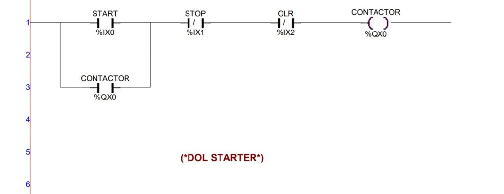
Ladder Diagram:

Making the Ladder Diagram:
In the digram there are three inputs, i.e. START, STOP, and OLR (over load relay) and one output coil, CONTACTOR.
From ladder line 1 a rung is connected with the input NO contact START push button switch (address %IX0), the input NC contact STOP push button switch (address %IX1) and input NC contact OLR switch (address %IX2) in series. This combination is connected in series with output coil CONTACTOR (address %QX0).
An input NO contact (address %QX0) of CONTACTOR output coil is connected across the START push button switch.
Observation:
Condition : 1 – When the motor is in OFF condition.

| START (Input) | STOP (Input) | OLR (Input) | CONTACTOR (Output : Motor) |
| 0 | 0 | 0 | 0 |
Condition : 2 – When the START switch is pressed ON then motor is in ON condition.

| START (Input) | STOP (Input) | OLR (Input) | CONTACTOR (Output : Motor) |
| 1 | 0 | 0 | 1 |
Condition : 3 – When the START switch is pressed OFF then also the motor remains in ON condition by getting power through NO contact across the START switch.

| START (Input) | STOP (Input) | OLR (Input) | CONTACTOR (Output : Motor) |
| 0 | 0 | 0 | 1 |
Condition : 4 – When the STOP switch is pressed ON, then motor turned OFF.

| START (Input) | STOP (Input) | OLR (Input) | CONTACTOR (Output : Motor) |
| 0 | 1 | 0 | 0 |
When the STOP switch is pressed OFF, the motor again goes to condition 1. If OLR is activated at ON condition of the motor then the motor will be OFF.
Remarks:
This ladder logic program is compiled and simulated on the softwere, SELPRO v.5.3.6. successfully.
Related posts:
Control Circuit Operation of Automatic Star-Delta Starter of Induction Motor using PLC
Study of Electromagnetic contactor, Thermal overload relay, Timer (Off delay, On delay), Push button...
Control and Power Circuit for Jogging Operation, Forward & Reverse Rotation of Sq. Cage Induction Mo...
To Make & Test the Working of Single Phase Preventer Using Contactor Control.
Views: 62

You need to be a part of a contest for one of the best blogs on the net. I will highly recommend this blog!
thank you for the information