Experiment No.: 5
Experiment Name:
Verification of the function of SR, D, JK and T Flip-flops
Objective:
To verify the SR, D, JK & T flip-flop circuits with truth table.
Theory: A flip flop is an electronic circuit with two stable states that can be used to store binary data. The stored data can be changed by applying varying inputs. Flip-flops and latches are fundamental building blocks of digital electronics systems used in computers, communications, and many other types of systems.
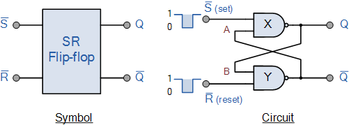
SR Flip-flop: The SR flip flop is a 1-bit memory bistable device having two inputs, i.e., SET and RESET. The SET input ‘S’ set the device or produce the output 1, and the RESET input ‘R’ reset the device or produce the output 0. The SET and RESET inputs are labeled as S and R, respectively.
The SR flip flop stands for “Set-Reset” flip flop. The reset input is used to get back the flip flop to its original state from the current state with an output ‘Q’. This output depends on the set and reset conditions, which is either at the logic level “0” or “1”.
Logic Circuit of SR flip-flop:
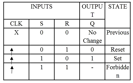
Truth Table of SR flip-flop:
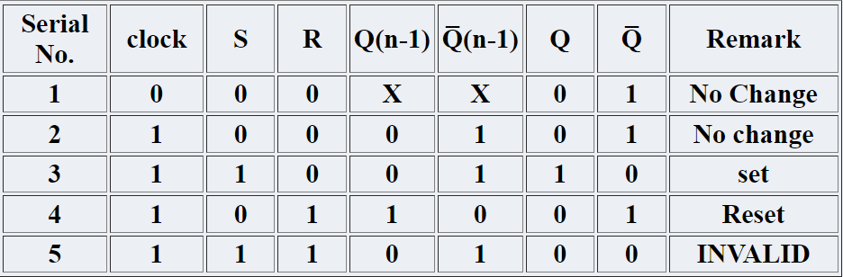
Observation Table SR Flip-flop:
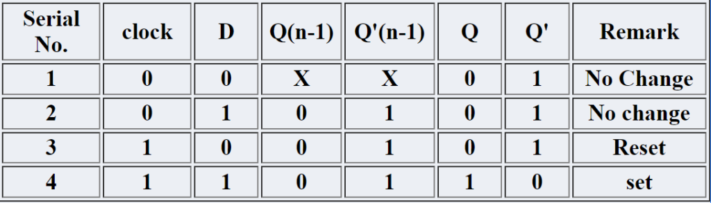
D Flip-flop: A D flip flop has a single data input. This type of flip flop is obtained from the SR flip flop by connecting the R input through an inverter, and the S input is connected directly to data input. The modified clocked SR flip-flop is known as D-flip-flop and is shown below. From the truth table of SR flip-flop we see that the output of the SR flip-flop is in unpredictable state when the inputs are same and high. In many practical applications, these input conditions are not required. These input conditions can be avoided by making them complement of each other.
Logic Circuit of D flip-flop:

Truth Table of D flip-flop:
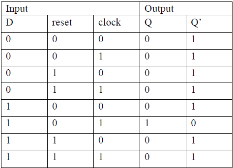
Observation Table of D Flip-flop:
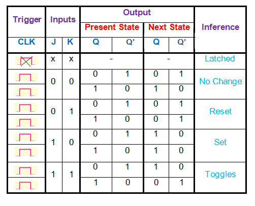
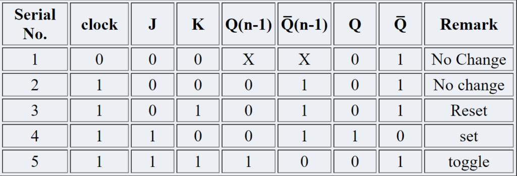
JK Flip-flop: In a RS flip-flop the input R=S=1 leads to an indeterminate output. The RS flip-flop circuit may be re-joined if both inputs are 1 than also the outputs are complement of each other as shown in characteristics table below.
Logic Circuit of JK flip-flop:

Truth Table of JK flip-flop:
Observation Table of JK Flip-flop:
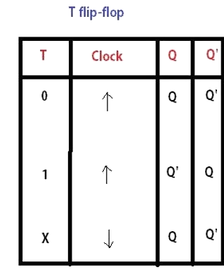
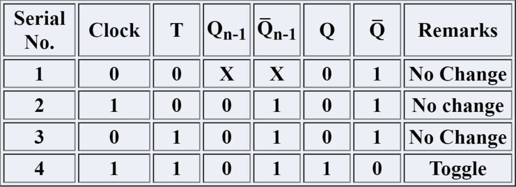
T Flip-flop: T flip-flop is known as toggle flip-flop. The T flip-flop is modification of the J-K flip-flop. Both the JK inputs of the JK flip – flop are held at logic 1 and the clock signal continuous to change as shown in table below.
Logic Circuit of T flip-flop:

Truth Table of T flip-flop:
Observation Table of T Flip-flop:
Apparatus Used:
| Sl. No. | Name of the Apparatus | Specification | Quantity | Maker’s Name |
| 1. | Digital Logic Trainer Kit | 230 V input | 1 | Sushama Electronics |
Remarks:
The truth table of SR, D, JK & T flip flops are verified successfully.
Views: 683
You need to be a part of a contest for one of the best blogs on the net. I will highly recommend this blog!