Experiment No.: 2
Experiment Name:
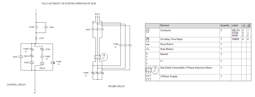
Making and Testing of Control and Power Circuit for Fully-Automatic Star-Delta Starter Operation of Cage Induction Motor using Contactor Control.
Objective:
To Make and Test Control and Power Circuit for Fully-Automatic Star-Delta Starter Operation of Cage Induction Motor using Contactor Control.
Circuit Diagram:
Making the Circuit:
Control Circuit:
- A start push button switch (NO) (START) is connected in series with stop push button switch (NC) (STOP) with the main contactor (MAIN) in series across any phase (T) and neutral (N). The NO contact of MAIN is connected across the START p.b. swich.
- Across the MAIN contactor, an on delay timer (TIMER) is connected and set time is 10 sec.
- Across this combination a contactor (STAR) is connected in series with two contacts. One is NC contact of TIMER and another is NC contact of another contactor (DELTA).
- Across this combination a contactor (DELTA) is connected in series with two contacts. One is NO contact of TIMER and another is NC contact of STAR.
Power Circuit:
- Three phase power line (R S T) is connected with U V W terminals of three phase Squirrel Cage Induction Motor through NO triple contact of contactor, MAIN.
- Z X Y terminals of the motor are short circuited through NC triple contact of on-delay timer, TIMER.
- NO triple contact of on-delay timer, TIMER is connected across power line R S T and Z X Y terminals of the motor.
Operation:
- When START switch is pressed and released, the MAIN contactor gets energised and NO contact of MAIN, (across the START switch) is closed, though this contact, the MAIN contactor gets power continuously. And the NO triple contact of MAIN is closed.
- At the same time the on-delay timer, TIMER gets energised and counts the preset time (say 10 sec). At the instant when the TIMER gets energised, then the NC triple contact of TIMER is in NC position until the count of the timer is done. Thus the machine starts in Star connected postion.
- When countdown of the timer is done, then the contacts of the TIMER change their position. i.e. from NO to NC and vice-versa. Then the NC triple contact of the TIMER is opened, and at the same time NO triple contact of the TIMER is closed, thus the motor is now connected in delta. And the motor is now continues to run in DELTA connected postion.
- When the STOP switch is pressed and released, then the MAIN contactor and TIMER are disconnected from the supply, and the motor is stopped.
Remarks:
The control and power circuit of this connection is made in EKTS softwere and tested successfully.
Views: 68