Experiment No.: 6
Experiment Name:
Use Voltmeter, Ammeter to Determine Load Resistance for Maximum Power Transfer for a Given Circuit by Applying Maximum Power Transfer Theorem.
Objective:
To verify Maximum Power Transfer Theorem.
Theory:
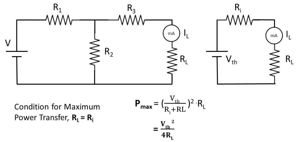
The Maximum Power Transfer theorem may be stated as follows, “A resistive load will absorb maximum power from a network when the load resistance is equal to the resistance of the network as viewed from the output terminals, with all energy sources removed leaving behind their internal resistance”.
Circuit Diagram:
Observation Table:
| Sl. No. | Load resistance (RL) (Ω) | Load current (IL) (mA) [Observed] | Load current (IL) (mA) [Calculated] | Power (W) [Observed] | Power (W) [Calculated] |
| 1. | 47 | 91.38 | 88 | 0.3924 | 0.3639 |
| 2. | 75 | 76.57 | 74.2 | 0.4397 | 0.4142 |
| 3. | 100* | 67.2 | 65 | 0.4515 | 0.4225* |
| 4. | 120 | 60.4 | 59 | 0.4377 | 0.4177 |
| 5. | 150 | 53.3 | 52 | 0.4262 | 0.4056 |
For resistance RL=100 Ω, power will be maximum i.e. 0.4515 W. Accoding to Maximum Power Transfer Theorem, RL= Ri = 100 Ω
Calculation:
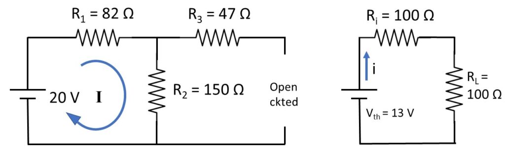
I = 86.2 mA
Vth = 12.93 V = 13 V (approx)
Ri = 47+(82||150) = 100 Ω
i= 13/200 = 65 mA, P=0.4225 W
Apparatus Used:
| Sl. No. | Name of the Apparatus | Specification | Quantity | Maker’s Name |
| 1. | Network theorem trainer kit | 0-20 V | 1 | M.E.W. |
| 2. | Digital Multimeter | 0-750 V AC, 0-1000 V DC, 0-10 A | 1 | Akademika |
Remarks:
The observed values and calculated values are nearly same. The difference between the is for instrumental and observational error. Neglecting this error Maximum Power Transfer Theorem is verified successfully.
Views: 1107