Experiment No.: 4
Experiment Name:
Use of Voltmeter, Ammeter, Wattmeter to Determine Active, Reactive and Apparent Power
Consumed in Given R-L-C Series Circuit and Draw Phasor Diagram.
Objective:
- To use voltmeter, ammeter, wattmeter to determine active, reactive and apparent power
consumed in given R-L-C series circuit. - To draw the phasor diagram of that circuit.
Theory:
Let V volts (rms) be applied to an R-L-C series circuit and the current flowing through the circuit be I amps. The impedance Z=V/I. If voltage across resistor is VR then R=VR/I
If voltage across inductor is V r,L, the impedance of the inductor coil is given by
Vr,L/I=√(r2+XL2)
Again the voltage across the resistance R and coil VR, L, then
Vr,L/I=√((R+r)2+XL2 )
From the above two equation the value of R and XL can be found out. If the voltage across the capacitor is VC then the reactance of the capacitor is given by XC=VC/I. hence the value of capacitance C=1/ωVC where ω=2πf is the angular frequency. the power factor is given by (R+r)/Z. If VC>VL, The pf is leading otherwise lagging.
The power consumed P=I2(R+r) or VI cos Ø
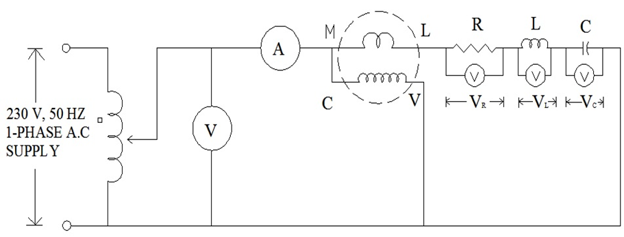
Circuit Diagram:
Procedure:
- The circuit is connected as shown in the circuit diagram with resistor, the inductor coil and capacitor in series.
- The variac is adjusted to zero output position and the circuit is switched on.
- A suitable voltage is applied from the variac so that a reasonable current flows through the circuit. The output voltage of the variac and voltage across the resistor, inductor and the capacitor are noted along with the current.
- Different readings are taken by varying voltage from the variac.
- Readings are noted from the data sheet.
Observation Table:
| Sl no | Voltage (V) | Current (mA) | Frequency (kHz) | R (Ω) | L (mH) | C (nF) | VR (V) | VR (V) | VC (V) | PF = cos Ø | Active power (mW) [VIcosØ] | Reactive power (mVAR) [VIsinØ] | Apparent power (mVA) [VI] |
| 1. | 5.02 | 9.09 | 13.05 | 546 | 7.75 | 22.08 | 4.67 | 4.22 | 4.2 | 0.98 | 44.71 | 9.034 | 45.62 |
Calculation:
XL = 2πfL = 2π×13.05×103×7.75×10-3= 635.46 Ω
XC = 1/2πfC = 1/(2π×13.05×103×22.08×10-9)= 552.34 Ω
cos Ø = R/Z = R/√(R2+(XL – XC)2) = 546/√(5462+(635.46 – 552.34)2) = 546/552.29 = 0.98 lag
Active power = VIcosØ = 5.02×9.09×10-3×0.98 = 44.71 mW
Rective power = VIsinØ = 5.02×9.09×10-3×0.198 = 9.034 mVAR
Apparent power = VI = 5.02×9.09×10-3 = 45.62 mVA
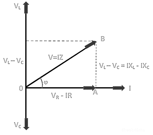
Phasor Diagram:
Apparatus Used:
| Sl. No. | Name of the apparatus | Quantity | Specification | Makes name |
| 1. | Single phase variac | 1 | 230/0-270 V ac | |
| 2. | LCR Trainer Kit | 1 | Sushama Electronics | |
| 3. | Digital Multimeter | 3 | 0-750 V, 10 A | Akademika |
| 4. | Wattmeter | 1 | Digital | |
| 5. | LCR Meter | 1 | Digital | Metravi |
| 6. | Connecting Probes | 10 | RGP-2 |
Remarks:
- The phasor diagram of different voltage and current for at least two observation are drawn in the graph paper.
- The value of power factor and magnitude of the supplied voltage are found from phasor diagram.
Views: 468
Nice for information
Thanks for information