Experiment No.: 5
Experiment Name:
Use voltmeter, ammeter to determine current through the given branch and voltage across the given element of circuit by applying Superposition Theorem.
Objective:
To verify Superposition theorem.
Theory: This theorem may be stated as follows, “In a network resistance containing more than one generator (or source of emf) the current which flows at any point is the sum of all the currents which would flow at the point if each generator where considered seperately and all the other generators replaced for the time being by resistors equal to their internal resistance.”
Circuit Diagram:
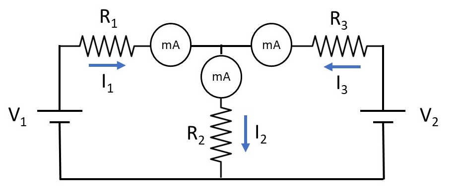
Observation Table: R1 = 112 Ω, R2 = 53 Ω, R3 = 100 Ω
| Sl. No. | Voltage Source | I1 (mA) | I2 (mA) | I3 (mA) |
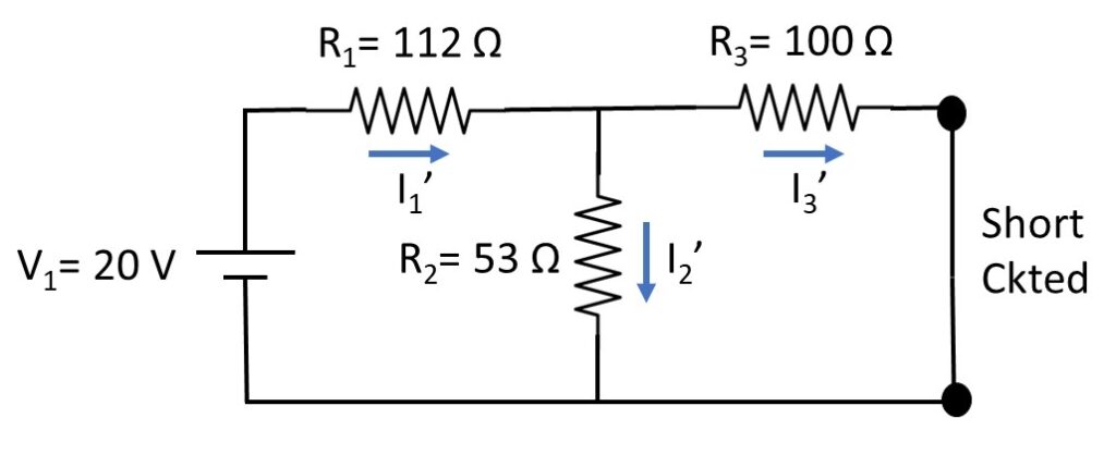
| 1. | V1 = 20 V acting alone | 130 | 90 | 47 |
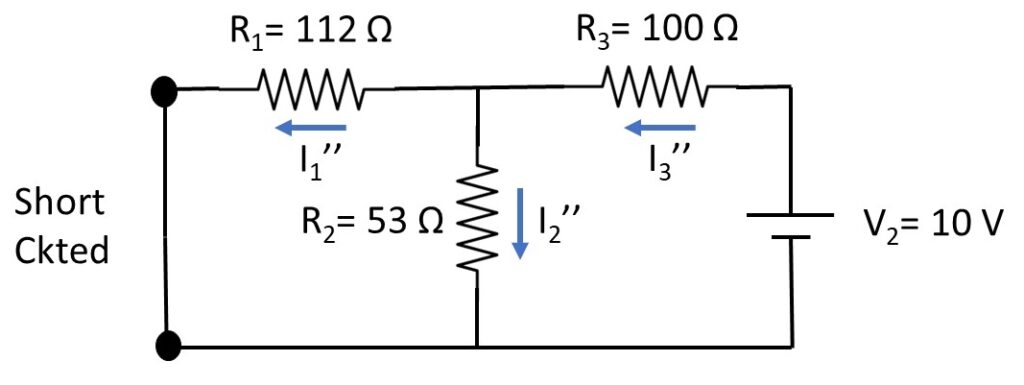
| 2. | V2 = 10 V acting alone | 20 | 50 | 73 |
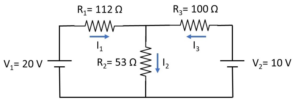
| 3. | V1 and V2 both are acting | 115 | 140 | 25 |
Calculation:
When 20 V source is acting alone:
When 10 V source is acting alone:
When 10 V & 20 V sources both are acting:
According to Superposition Theorem,
I1 = I1‘- I1” = 112.76 mA
I2 = I2‘+ I2” = 139.06 mA
I3 = I3‘- I3” = 26.29 mA
Apparatus Used:
| Sl. No. | Name of the Apparatus | Specification | Quantity | Maker’s Name |
| 1. | Network theorem trainer kit | 1 | M.E.W. | |
| 2. | Milli-ammeter | PMMC, 0-150 mA | 3 | |
| 3. | Resistor | 112 Ω, 53 Ω, 100 Ω | 3 |
Remarks:
The observed values and calculated values are nearly same. The difference between the is for instrumental and observational error. Neglecting this error Superposition Theorem is verified successfully.
Views: 842