
Experiment No.: 3
Experiment Name:
Making & testing the working of single phase preventer using contactor control.
Objective:
To make & test the working of single phase preventer using contactor control.
Theory:
Single phase preventer is used to protect the induction motor from single phasing fault. It is a very dangerous fault to the electrical motor and Which damages the motor stator winding rapidly. Generally single phasing is nothing but a motor runs when one of the supply is disconnected due to open circuit or improper contact in switch or other electrical equipment failure.
Normally, the motor runs with the three phase supply and which takes balance current in each phase winding. Consider one of the fuse has blown. But the motor still in a rotating position which tries to rotates at the same speed. At that same time, the absence phase current will be shifted to the remaining live phases. Therefore, the current in the other phases increases up to 3 times its normal value instantly. This is called a single phasing fault.
The single phasing leads to an unbalanced current in the motor stator. The component which is present in this unbalanced current called negative sequence component. This negative sequence component creates the magnetic flux opposite to the main flux. This results in double frequency currents to induce in the rotor to cause its heating.
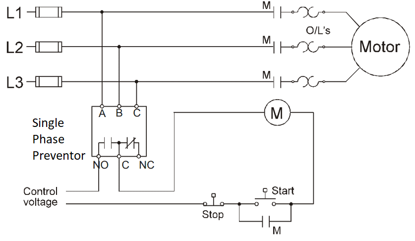
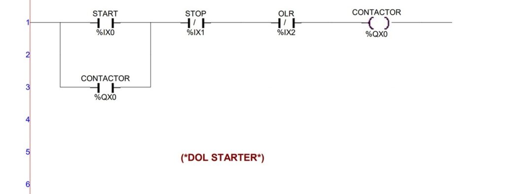
Circuit Diagram:
Operation and Observation:
- When the system is normal, the START push button switch is pressed and released, then the main contactor coil, M gets energized and NO contact across the START is closed and at the same time the NO of single phase preventor is closed and NC is opened and the triple contact of the M contactor is closed. So the motor gets started.
- Now, when there is one or two phase are missing, then the closed NO contact of the single phase preventer gets opened and the opened NC contact will be closed. As a result the M contactor circuit is now opened and the contactor coil M gets de-energized and the contacts related this M, change there position and the motor stopped.
- Until the fault is cleared, the single phase preventer will prevent to make the circuit.
Apparatus Used:
| Sl No. | Name of the Apparatus | Specification | Quantity | Maker’s name |
| 1. | Single Phase Preventor | 3 phase, 1NO, 1NC, 415 V, 50 Hz, DIN mount | 1 | GiC |
| 2. | Contactor Block | 3 phase, 4 NO, 415 V, 63 A, 50 Hz, DIN mount | 1 | Schneider |
| 3. | Induction Motor | 3 phase, 1 HP, 415 V, 1440 rpm, | 1 | Triple-D |
| 4. | Connecting Cables | 2.5 sq. mm, 1100 V grade, PVC insulated, FRLS | as required | MARU |
| 5. | Start and Stop Switch | 1 NO, 1 NC Push Button Switch | 2 |
Remarks: The circuit is made as per the diagram shown and the circuit is tested by creating single phase fault by swiching off any one phase at a time. The preventer works perfectly by disconnecting the motor from supply after occuring the fault.
Views: 112
Related posts:
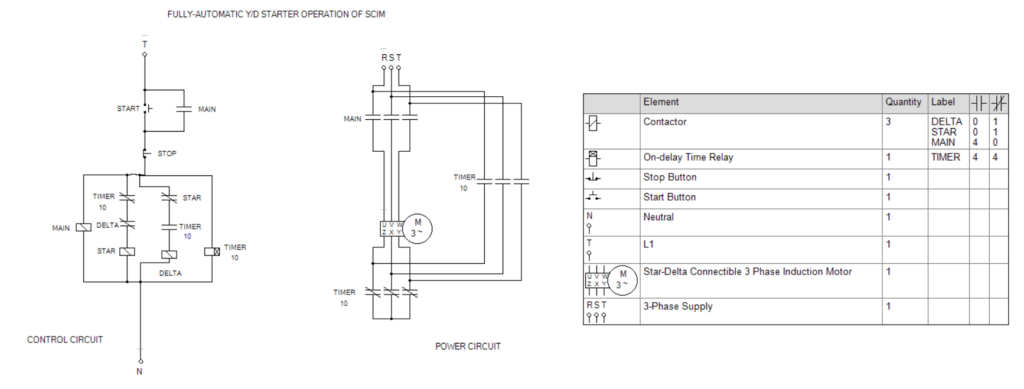
Control and Power Circuit for Fully-Automatic Star-Delta Starter Operation of Cage Induction Motor u...
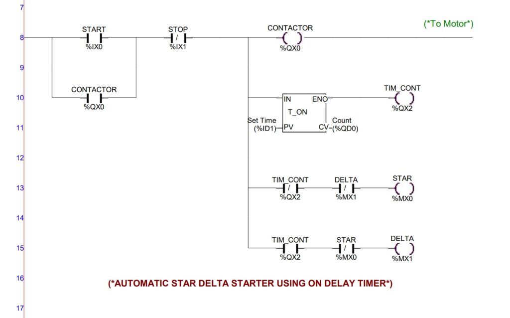
Control Circuit Operation of Automatic Star-Delta Starter of Induction Motor using PLC
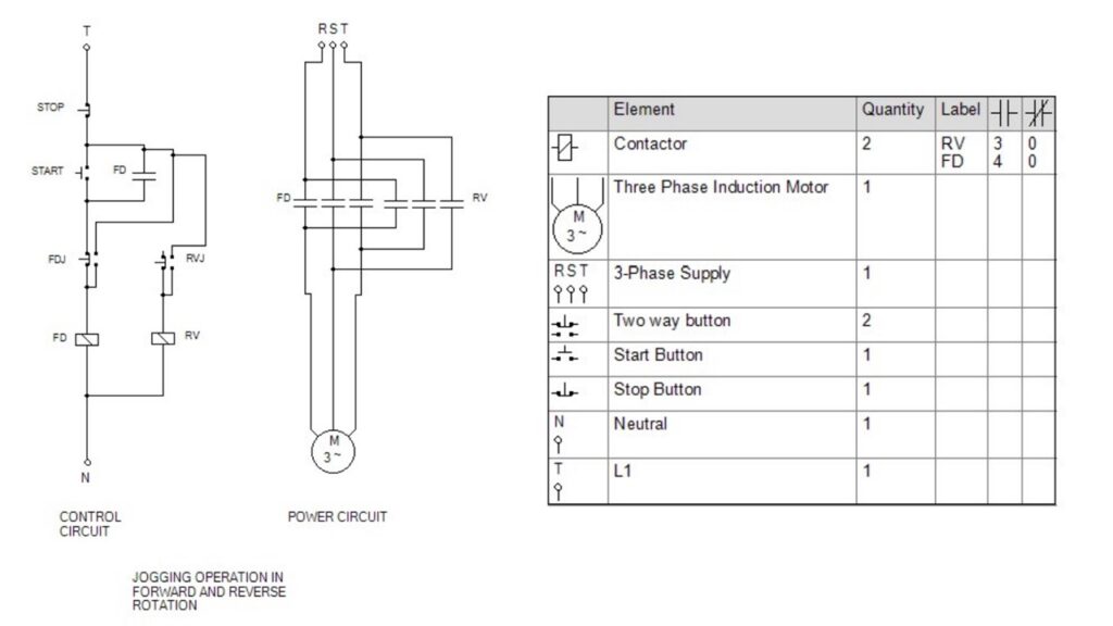
Control and Power Circuit for Jogging Operation, Forward & Reverse Rotation of Sq. Cage Induction Mo...















Thanks for sharing. I read many of your blog posts, cool, your blog is very good.
Your point of view caught my eye and was very interesting. Thanks. I have a question for you.