Experiment No.: 1
Experiment Name:
To study control components – Electromagnetic contactor, Thermal overload relay, Timer (Off delay, On delay), Push button Switches, Solenoid valve, MCB.
Objective: To study,
- Electromagnetic Contactor
- Thermal Overload Relay
- Timer (Off Delay & On Delay)
- Push Button Switch
- Solenoid Valve
- MCB
Therory:
1. Electromagnetic Contactor:
A contactor can be best described as a magnetically closed switch. It is the basic unit upon which the motor starter is built. Contactors are also used for switching ON and OFF of heavy loads like furnaces, heaters, capacitors, etc. A contactor consists of an electromagnet, a movable
core, sets of stationary and moving contacts and an arc quenching structure. Contactors can be broadly classified in to two general types:
(a) Solenoid type (b) Clapper type .
• The movable contacts are attached to the movable core of a magnet.
• When the electromagnet coil is energized, the movable core is pulled to the stationary core, thus closing the contacts. Mounting of contacts in horizontal plane reduces the size of the contactor.
• When the coil is energized, plunger moves up, moving contacts mounted on plunger also moves up and closes the normally open contacts.
• At the same time normally-closed contacts open. When the coil is deenergized contacts are broken and they come back to their normal position by the pull of gravity.


2. Thermal Overload Relay:
This is the most widely used relay because of its simple construction and minimal cost.
• The relay consists of three bimetallic strips with current coils wound on them.
• The whole of the assembly is mounted on a Bakelite enclosure.
• Bimetallic strips comprising two dissimilar metals having different thermal coefficients of expansion are used for the three phases.
• Current flowing through the coils heat the bimetallic strips.
• Upper ends of the strips are firmly held while lower ends are free to move. • When temperature of the strips increases due to current flowing through the coils, the strips bend towards right due to different expansion of metals. When the strips bend towards the right, the tripping mechanism gets actuated and opens the relay contact.


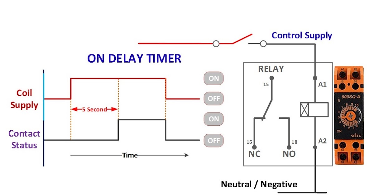
3. Timer (Off Delay and On Delay):
• In time delay relays the relay contacts change over their position after a pre set delay from the time of energisation or de-energisation of the relay coil.
• Time delay relays are also commonly known as Timers.
• Timer can be of ON-delay or an OFF-delay type.
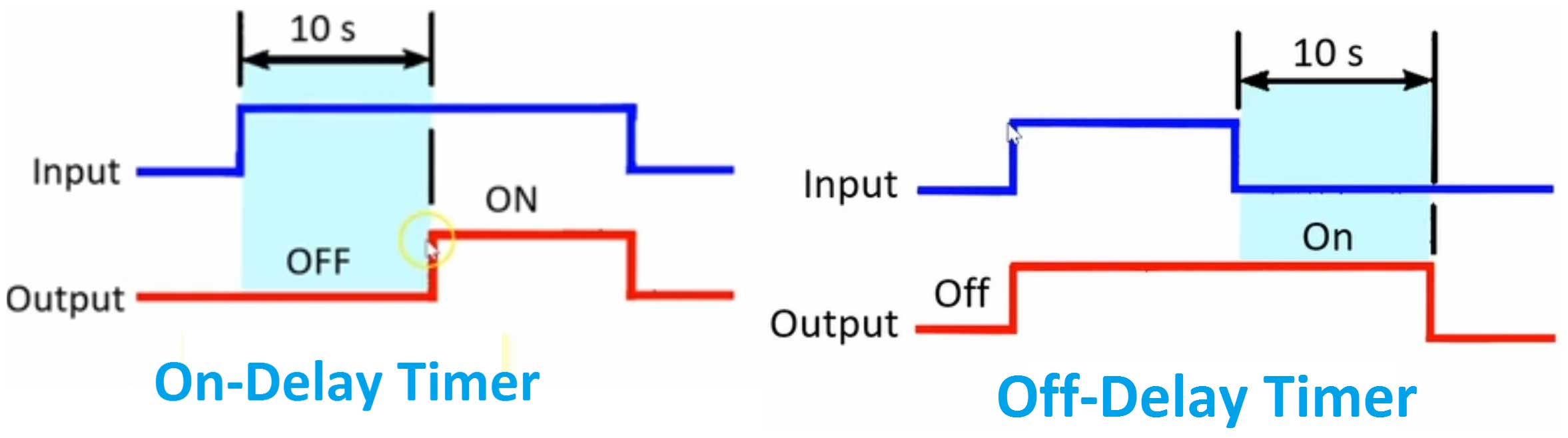
• ON-delay type : the contacts change over after a pre-set delay after energisation.
• OFF-delay type : the contacts change over after a pre-set delay from the instant of de-energisation.
• Besides the delayed contacts a timer can also have another set of contacts which operate as in an ordinary voltage relay. These are known as instantaneous contacts as they changeover their positions instantaneously when the timer is energised or de- energised. • ON-delay timer is normally in de-energised condition. When the timer is energised, after a pre-set delay the contacts change over their positions. Contact 1 will become closed and contact 2 will open. However, when the timer is de-energised contacts change over almost instantaneously.
• OFF-delay timer is normally in energised condition. Thus, normally, contact 3 will be closed and contact 4 will be open. When the timer is de-energised the counting starts and after the pre-set delay, contacts 3 will open and contact 4 will close. • Normally, most circuits require ON-delay timers. Applications requiring OFF-delay timers can also be covered by ON-delay timers with suitable modifications in the circuitry. However, OFF delay timers can, in few cases, simplify circuitry and thereby reduce the cost.
• When a timer continues to repeat its sequence of operation till the supply is switched off, it is called a cycle timer.
• The non-cyclic timers operate only for one timing cycle when they are switched on.
• Majority of applications require ON-delay, non-cyclic, non-manual reset type timers.
• There are four different types of timers utilizing different operating principles. These timers are thermal timers, pneumatic timers, electronic timers and motor driven (synchronous) timers.

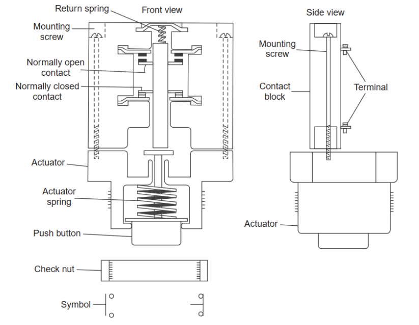
4. Push Button Switch:
• A pilot Device, provides control of an equipment by pressing an actuator which looks like a button.
• 2 parts . Mechanical part and Electrical contact block.
• 2 types. Momentary contact spring type and Maintained contact type.
• The momentary-contacts spring returned push button remains actuated as long as the button is
physically held pressed by the human operator. Once the button is released the contacts return to
their normal position.
• Maintained contact push buttons are held actuated by some latching mechanism even when the
operator releases the pressure on the push button. Such units consist of two push buttons.
• The contact block has two contacts, one normally open (NO) and the other normally closed (NC). When the push button is pressed, NC contacts opens and NO contact closes. When the push button is released a spring inside the actuator assembly brings back the push button and a spring inside the contact block brings the contacts back to their normal position.
• Red – Stop, Green – Start
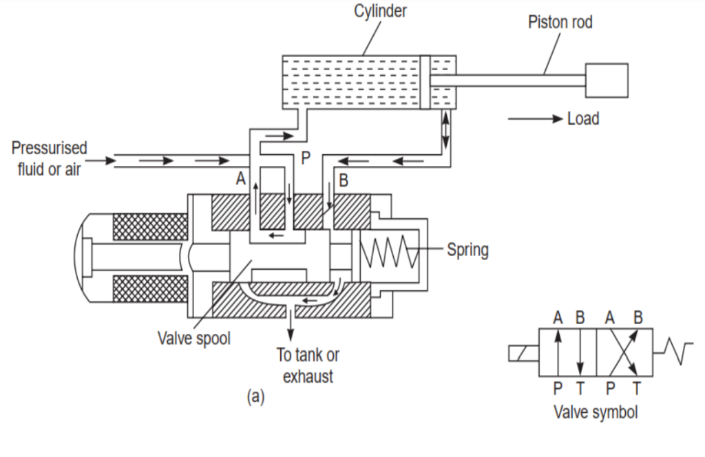
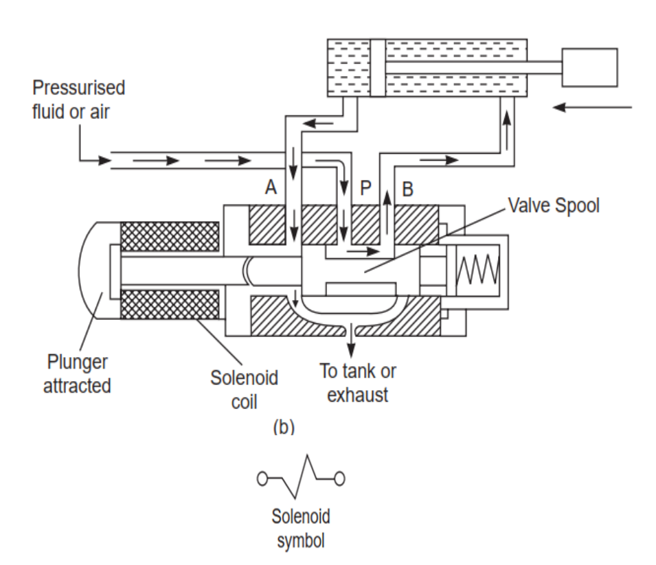
5. Solenoid Valve:
• Solenoid valves are electromechanical devices which are used to obtain mechanical movement in machinery by utilizing fluid or air pressure.
• The fluid or air pressure is applied to the cylinder piston through a valve operated by a cylindrical electrical coil.
• The electrical coil along with its frame and plunger is known as the solenoid and the assembly of solenoid and mechanical valve is known as solenoid valve.
• Solenoid valves are of two types:
(i) Single solenoid spring return operating valve,
(ii)Double solenoid operating valve.
• A single solenoid spring return valve in its de-energised condition is shown.
• In the de-energised condition, the plunger and the valve spool position are as shown in (a). • In this position of spool, port P is connected to port A and port B is connected to tank or exhaust (i.e., atmosphere) if air is used.
• Spring pressure (S) keeps the spool in this condition as long as the coil is deenergised. Fluid pressure from port P through port A is applied to the left side of the cylinder piston.
• Thus the cylinder piston moves in the right direction. • Now when the solenoid coil is energised, plunger is attracted and it pushes the spool against spring pressure.
• In this position of spool, port A gets connected to tank and port P gets connected to port B.
• Thus pressure is applied to the cylinder piston from the right and moves the piston rod to the left.
• At the same time fluid in the other side is drained out to the tank.
• When the solenoid coil is again de-energised, the spring (S) will move the spool to its original position .
6. MCB:
• A miniature circuit breaker (MCB) automatically switches off the electrical circuit during an abnormal condition of the network.
• Miniature circuit breaker construction is very simple, robust and maintenance free.
• MCB is much more sensitive to overcurrent than a fuse and does not require manual replacement after operation.
• In the case of MCB, quick restoration is possible by just switching on operation.
• Handling MCB is more electrically safe than fuse .
• Because of too many advantages of MCB over fuse units, in modern low voltage electrical network, miniature circuit breaker is mostly used instead of fuse unit.
• Two mode of operations are there for MCB. One due to thermal effect of over current and other due to electromagnetic effect of over current.
• A bimetal provides protection against overload current and an electromagnet provides protection against short circuit current.
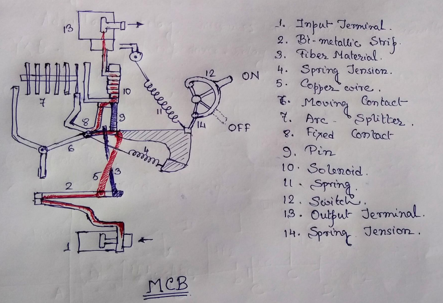
Working principle
• The over current protection is achieved by the bi-metallic strip. When over current flows for a long time the thermal protection is achieved by the bi metallic strip. It gets heated and bends. This deflection of the strip enables the operation of MCB.
• In case of short circuit the current rises abruptly. This activate the magnetic control. The plunger of the solenoid is displaced electro-magnatically. The plunger strikes the trip lever causing immediate release of latch mechanism consequently open the circuit breaker contacts.
• Miniature circuit breakers (MCB) form a special group of LV circuit breakers, not only because of
their small size and easy installation, but mainly due to their small rated currents (I r=4…125 A)
combined with high breaking capacity (I SC=3…25 kA).
Related posts:
Control and Power Circuit for Fully-Automatic Star-Delta Starter Operation of Cage Induction Motor u...
Control Circuit Operation of Automatic Star-Delta Starter of Induction Motor using PLC
Control Circuit Operation of DOL Starter of Induction Motor Using PLC
To Make & Test the Working of Single Phase Preventer Using Contactor Control.
Views: 297