Experiment No.: 4(B)
Experiment Name:
Determination of equivalent circuit parameters of single-phase transformer by performing Short Circuit test
Objective:
The objective of the experiment is to find out
- Copper loss at any load
- Different parameters of the transformer with respect to high voltage side & low voltage side (i.e. equivalent resistance, equivalent impedance etc.), with the help of ammeter, voltmeter, wattmeter and dimmer stat.
Theory:
Transformer is a static AC machine. It has two winding, one is low voltage side and other is high voltage side. With the help of auto-transformer the supply voltage is gradually increased on the high voltage side of the transformer by 5% to 10% of the normal rated voltage on high voltage side, which gives the full load current on high voltage side. As the voltage is small, so the mutual flux is also smaller and hence the core loss is very small. The magnitude of the voltage needed to circulate the full load current will be very small. The reading of the wattmeter when the short circuit is performed at rated full load current will be approximately equal to full load copper loss. From short circuit test data, the equivalent resistance, reactance and impedance of the transformer can be found out with respect to high voltage side as well as the low voltage side.
Circuit Diagram:
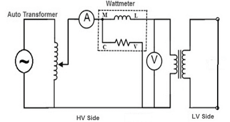
Experimental Setup for the Short Circuit Test on a 1-Φ Transformer:
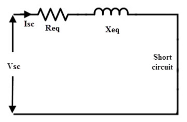
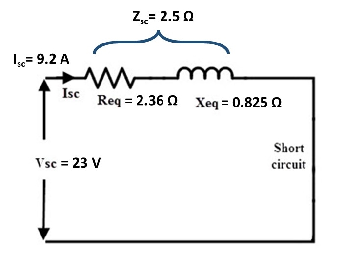
When the transformer secondary terminals are short circuited, the secondary current is large, because only the transformer winding impedance limits it. Reffering to the figure below, and neglecting the magnetizing current, the short circuit current (= current with the secondary short circuited) is given by:
Short circuit current = Voltage / Transformer leakage impedance
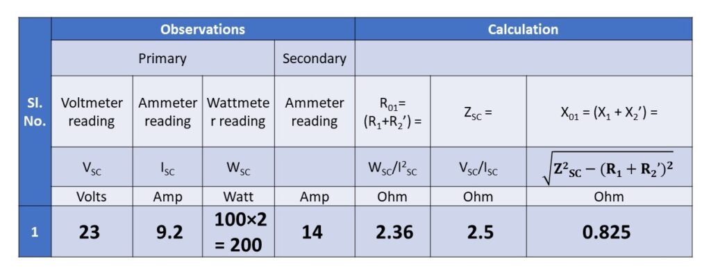
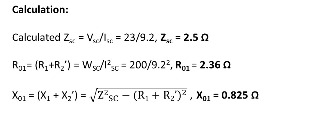
This current is large, since the transformer leakage impedance (= R+jX) is usually small. To keep this within limits, the only way is to apply a low voltage to the transformer primary. Since the voltage applied is low, the magnetizing current through the no load branch in its equivalent circuit is low and hence it can be ignored. The equivalent circuit then become as shown in figure above. This is obtained by using the equivalent circuit (phasor diagram) of the transformer with purely resistive load and putting ZL’ = 0. Measuring power input (WSC), the short circuit current (ISC) and voltage applied (VSC), the parameters (R1+R2’ and X1+X2’) are related as below:
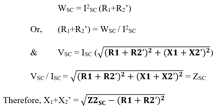
When the primary side resistance R1 is measured, the secondary side resistance R2’ can be separated from the total resistance.
R2’ = (R1 + R2’) – R1
The leakage reactances are generally assumed to be equal and hence
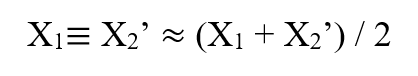
Thus all the parameters can be found.
Experimental Procedure:
- Connect as shown in the circuit diagram
- Set the variac output to zero and switch on the supply
- Apply a low voltage, setting the variac output suitably and watch the ammeters
- Apply such a voltage, which circulates the rated current
- Note the reading of the wattmeter, voltmeter and the two ammeters
- Calculate the total resistance (R1 + R2’) and the reactance (X1 + X2’) from these readings
- Measure the resistance of the primary winding using a battery, (or a low voltage DC source) and an ammeter.
Observation Table:
Equivalent Circuit :
Apparatus Used:
| Sl. No. | Name of the Apparatus | Specification | Quantity | Maker’s Name |
| 1. | Transformer | Single Phase, 230/115 V, 5 A | 1 | |
| 2. | Variac | 230/0-270 V | 1 | |
| 3. | Digital Multimeter as Ammeter | 0-750 V AC, 0-1000 V DC, 0-10 A | 1 | Akademika |
| 4. | Voltmeter | MI type, 0-300 V | 1 | Sushma |
| 5. | Wattmeter | EDM type, 0-750-1500-3000 W, 150-300-600 V, 5-10 A | 1 | MECO-G |
| 6. | Control Panel | 230 V, 50 Hz | 1 | M.E.W. |
Remarks:
The experimental results obtained from the short circuit tests were not evaluated. It would be possible to test the maximum efficiency of the transformer is operating at maximum efficiency. The actual efficiency of the transformer could be found by dividing the power out by the power in. The procedure used to find the parameter values of the non-ideal transformer equivalent circuit model allows the engineer to more efficiency design transformer circuits. Modelling and simulation are more accurate when the non-ideal parameters are used. This means that designs can be optimized prior to implementation.
Views: 1181