Experiment No.: 1
Experiment Name: Plot the O.C.C. of a D. C. Generator & find the Critical Resistance.
Objective:
- To plot open circuit characteristics of a DC shunt generator
- To find critical resistance from the characteristics curve
Theory:
In a DC Generator an expression for the voltage generated (E) in the armature winding can be written as- E= PΦZN/60A volt. Where Φ= Flux per pole in weber, Z= No. of armature conductors, N= Speed in rpm, P= No. of poles, A=No. of parallel paths.
For a generator, which is, running at constant speed the above expression can be written as, E= K.Φ or, E=K.B
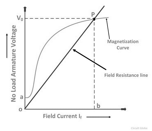
Where B is the flux density in the air gap. The flux is established due to field mmf Nf If . Where Nf is the number of field turns and If is the field current. Due to this a field intensity H is established and H= Nf If / L, where L is the mean length of the magnetic path per pole. From the above, E α B and B is a function of H, while H α If. Thus the relation between E and If , must be similar to that between B and H for the magnetic circuit of the machine. A typical magnetization curve is shown in the figure. This characteristic is also known as the Open Circuit Characteristics (O.C.C.) curve, since the armature is open circuited.
Circuit Diagram:

Observation Table:
Speed of the generator = 1500 r.p.m.
| Sl. No. | If field current (A) | No load voltage across armature, Eg (V) |
| 1. | 0 | 28.04 |
| 2. | 0.04 | 85 |
| 3. | 0.08 | 155 |
| 4. | 0.12 | 190 |
| 5. | 0.16 | 210 |
| 6. | 0.2 | 230 |
| 7. | 0.24 | 235 |
| 8. | 0.28 | 240 |
| 9. | 0.32 | 250 |
| 10. | 0.36 | 250 |
| 11. | 0.38 | 250 |
Characteristics Graph:

Calculation:
Critical resistance = Voltage/ current from the open circuit characteristics
Apparatus Used:
| SL NO | Name of the Apparatus | Specification | Qty. | Maker’s Name |
| 1 | DC Motor | 3 HP, 220 V DC Shunt | 1 | M.E.W. |
| 2 | DC Generator | 3 kW, 220 V DC Shunt | 1 | M.E.W. |
| 3 | Ammeter | PMMC type, 0-1 A | 1 | |
| 4 | Voltmeter | PMMC type, 0-300 V | 1 | |
| 5 | Tachometer | Non contact type, Digital | 1 | Metrix+ |
| 6 | Control Panel | 230 V AC | 1 | M.E.W. |
| 7 | Connecting Cables | Banana Jack | As required |
Remarks:
1. The method is applicable to both, the ‘series’ as well as the ‘shunt’ generator. The field winding is separately excited in this method. In case of series generator, the field circuit has to be suitable for carrying the rated current. For series generator, instead of potential divider arrangement, a variable resistance in series with the field winding is used to change the field current. The resistance of suitable current should be chosen.
2. The reading should be taken with field current increasing only. This is because of the hysteresis effect, due to which the curve with readings taken in the decreasing order of the field current lies little above the curve with increasing order of the field current.
Related posts:
Control the Speed of DC Shunt Motor BELOW Rated Speed & Draw the Speed Characteristics
Control the Speed of DC Shunt Motor ABOVE Rated Speed & Draw the Speed Characteristics
Starting and Reversing of DC Motor
Parallel Operation of Two 1-ph Transformers to Determine the Sharing of Load Current, Apparent and R...
Views: 786