Experiment No.: 6(B)
Experiment Name:
Parallel Operation of Two 1-ph Transformers to Determine the Sharing of Load Current, Apparent and Real Power.
Objective:
- To perform parallel operation of two 1-ph transformers
- To determine the sharing of load current, apparent power and real power
Theory:
Parallel operation of transformers is used for load sharing. The transformers are connected in parallel on both primary and secondary side. Following conditions to be satisfied during the parallel operation of transformers.
- Same polarities should be connected.
- The two transformers should have same voltage ratio.
- The percentage impedance should be same.
- There should be no circulating current.
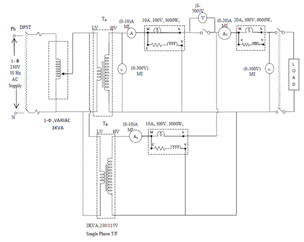
Circuit Diagram:
Procedure:
- Connect the circuit as shown in the diagram.
- Note down the readings of all wattmeters, ammeters and voltmeters for given load.
- Repeat the above test for different values of load.
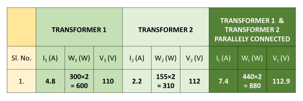
Observation Table:
Calculation:
Total load shared by both of the transformer (as per wattmeter reading)= 880 W
Total load shared by both of the transformer (calculated)= 600+310 = 910 W
The difference is due to instrumental error.
Load shared by Transformer 1(real power) = 600 W, % load shared = (600/910) x 100 = 65.93 %
Load shared by Transformer 2 (real power)= 310 W, % load shared = (310/910) x 100 = 34.06 %
Total Real Power = (600+310) = 910 W
Load shared by Transformer 1(apparent power) = 110×4.8 VA = 528 VA, % load shared = (528/774.4) x 100 = 68.18 %
Load shared by Transformer 2 (apparent power)= 112×2.2 VA = 246.4 VA, % load shared = (246.4/774.4) x 100 = 31.81 %
Total Apparent Power = (528+246.4) = 774.4 VA
Apparatus Used:
| Sl. No. | Name of the Apparatus | Specification | Quantity | Maker’s Name |
| 1 | Transformer | 1-Ø, 230/115 V, Shell type | 2 | |
| 2 | Variac | 230/0-270 V | 1 | |
| 3 | Ammeter (A1, A2) | 0-10 A, MI type | 2 | Sushma |
| 4 | Ammeter (A3) | 0-20 A, MI type | 1 | K.E.W. |
| 5 | Voltmeter (V1, V2) | 0-300 V, MI type | 2 | Sushma |
| 6 | Digital Multimeter as Voltmeter (V3) | 0-750 V AC, Digital | 2 | Akademika |
| 7 | Wattmeter (W1) | 0-750 W, 150-300-600 V, 5-10 A, EDM type | 1 | MECO-G |
| 8 | Wattmeter (W2, W3) | 0-750-1500-3000 W, 150-300-600 V, 5-10 A, EDM type | 2 | MECO-G |
| 9 | Control Panel | 230 V, 50 Hz | 1 | M.E.W. |
| 10 | Rheostat | 1 kW, Resistive wire wound | 1 | |
| 11 | Connecting Cables | Banana Jack | As required | |
| 12 | MCB as Paralleling switch | 16 A, 240 V, 50 Hz, C16 | 1 | Juvas |
Precaution:
- Transformers should be connected in such a way that they have same polarity.
- All connections should be neat and tight.
- Connecting leads should be perfectly insulated.
Views: 563
You need to be a part of a contest for one of the best blogs on the net. I will highly recommend this blog!