Experiment No.: 4(A)
Experiment Name: Determine Equivalent Circuit Parameters of Single-Phase Transformer by Performing O.C. Test
Objective:
To perform the O.C. test of a single- phase transformer with the help of an ammeter, voltmeter and a wattmeter and to find out the core loss of the transformer, different parameter at no load condition and to predetermine the performance of the transformer represented by its equivalent circuit.
Theory:
Transformer is a static AC machine. In this test normally the high voltage winding is left opened and all the meters are placed on the low voltage winding side (depending upon the availability of supply voltage in the lab). At no load, the current taken by the ammeter gives no load current (I0) whose value is very small w.r.t. full load current. The wattmeter gives the reading of the core loss of the transformer, which is constant at any load. The voltmeter indicated the rated voltage of the transformer at which side of the winding of the transformer, the meters are connected.
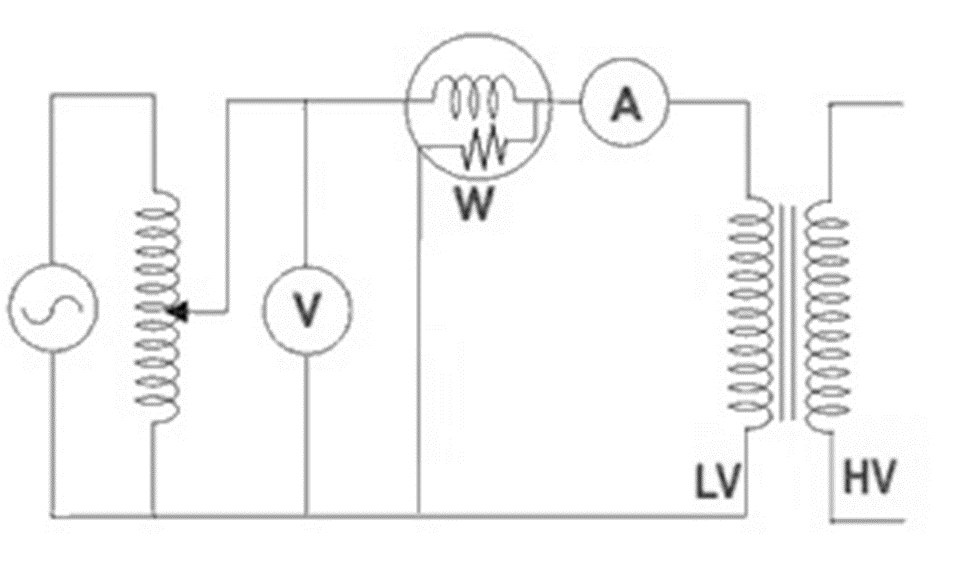
Experimental Setup for Open Circuit Test on a Single Phase Transformer:
Core loss depends upon the applied voltage. Since normal voltage is applied to low voltage side, so normal flux will be setup on the core, and the normal iron loss (core loss) will be occurred which are recorded by the wattmeter. Hence the wattmeter reading represents practically no load core loss, which is constant at any load.
Let, W0 = Wattmeter reading which gives iron loss or core loss
I0 = No load current
V0 = Rated voltage at no load on the low voltage side
cos Φ0 = No load power factor
Φ0 = Angular distance between I0 & V0
So, Wattmeter reading, W0 = V0 . I0. cos Φ0
Or, cos Φ0 = W0/V0 I0
By knowing the ‘Cos Φ0’, we can find out sinΦ0
Now, iron loss or working component of the current IW = I0 cosΦ0
The magnetising component of the current Iµ = I0 sinΦ0
There the no load resistance,
R0 = V0 / IW
And the leakage reactance, X0 = V0 / Iµ
The open circuit test is done on the low voltage side and the high voltage side is kept open, because it is safe and it requires low range meters which gives low cost for performing this test.
Circuit Diagram:
Procedure of the Experiment:
- Connect as shown in the circuit diagram
- Set the variac to zero output, and switch on the supply
- Set the variac to a suitable voltage output
- Watch the wattmeter, ammeter and voltmeter. Increase the variac output voltage gradually till the rated voltage is reached. With rated voltage applied to the primary side, take the readings of the wattmeter, ammeter and voltmeter
- Calculate R0 & X0 from this readings
Result & Calculation:
| Ammeter reading in Amp (I0) | Voltmeter reading in volt (V0) | Wattmeter reading in watt(W0) (M.F=1)* | No load power factor (cosΦ0) | IW=I0cosΦ0 | Iµ=I0sinΦ0 | R0=V0/IW | X0=V0/Iµ |
| 0.656 A | 115 V | 30×1=30 W | 0.397 lag | 0.2609 A | 0.6019 A | 440.78 Ω | 191.06 Ω |
No load vector diagram:

Apparatus Used:
| Sl. No. | Name of the Apparatus | Specification | Quantity | Maker’s Name |
| 1. | Transformer | Single Phase, 230/115 V, 5 A | 1 | |
| 2. | Variac | 230/0-270 V | 1 | |
| 3. | Digital Multimeter as Ammeter | 0-750 V AC, 0-1000 V DC, 0-10 A | 1 | Akademika |
| 4. | Voltmeter | MI type, 0-300 V | 1 | Sushma |
| 5. | Wattmeter | Digital | 1 | CABS Electra |
| 6. | Control Panel | 230 V, 50 Hz | 1 | M.E.W. |
Remarks: The measuring instruments are to be connected in low voltage side and high voltage side should be opened for open circuit test.
Related posts:
Views: 1142
Hello to every single one, it’s in fact a fastidious for me to pay
a visit this site, it includes useful Information.
Pretty section of content. I just stumbled upon your
web site and in accession capital to assert that I acquire in fact enjoyed account your blog posts.
Anyway I’ll be subscribing to your feeds and even I achievement you access consistently quickly.
I like the helpful info you provide in your articles.
I’ll bookmark your weblog and check again here regularly.
I am quite sure I’ll learn plenty of new stuff
right here! Best of luck for the next!
This info is priceless. How can I find out more?
I was recommended this blog by my cousin. I am not sure
whether this post is written by him as no one else know such detailed about my trouble.
You’re amazing! Thanks!