Experiment No.: 2
Experiment Name: Use of Clamp-on meter / digital multi-meter for measurement of AC/DC current, AC/DC voltage
Objective:
- To measure DC voltage and current
- To measure AC current by using Clamp-on meter
Theory:
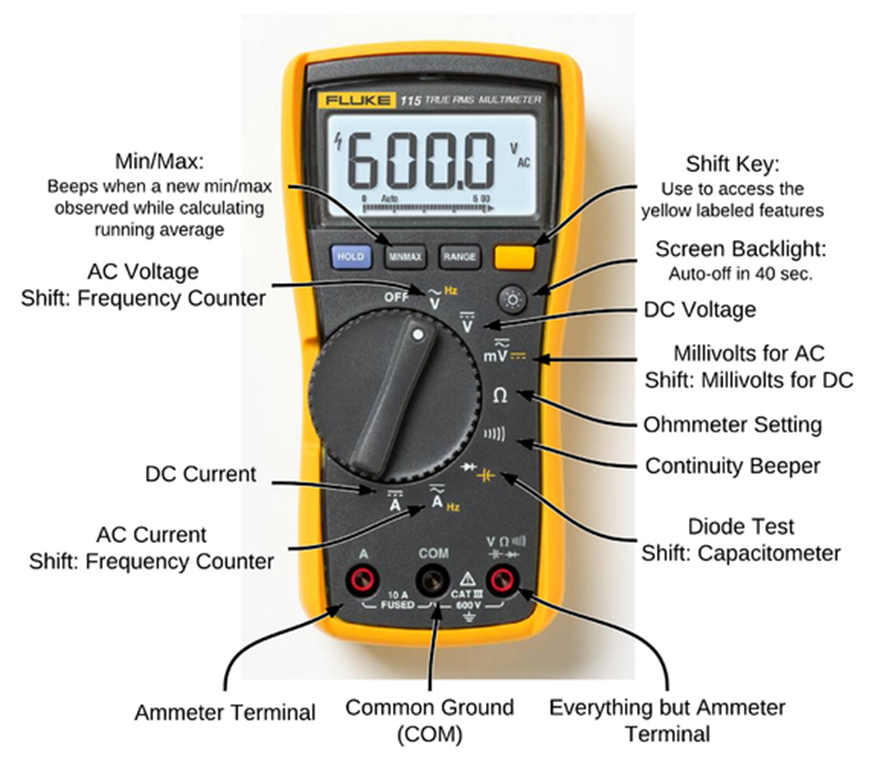
Multimeter:
Multimeter is a versatile compact form of electrical instrument which can measure multirange DC voltage, AC voltage, resistance and current in a circuit directly. The multimeter is also termed as ‘AVO’ meter or ‘multi-tester’. It is a battery operated instrument. The range of measurements can be performed with a suitable selector switch.
The most commonly used multimeter performs the functions of four multirange measurements i.e. DC voltage, Direct Current (in milli-amp), AC voltage and resistance. The multimeter is a portable instrument and gives the measurement value instantaneously. This instrument requires no external power supply. This instrument is a very sensitive one & gives high degree of accuracy. It is a indispensable instrument in the field of electrical maintenance jobs. It is also useful instrument for the technicians of electronics work.The multimeter may be digital or analogue type, of which digital multimeter is widely used.
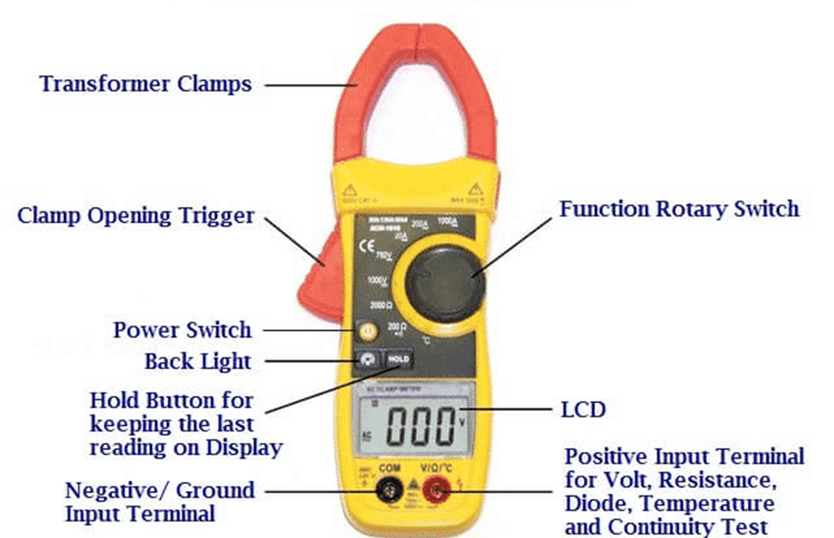
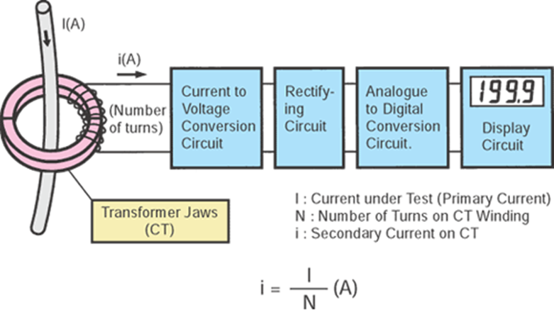
Clip-on Ammeter:
A current clamp or current probe is an electrical device with jaws which open to allow clamping around an electrical conductor. This allows measurement of the current in a conductor without the need to make physical contact with it, or to disconnect it for insertion through the probe. Current clamps are typically used to read the magnitude of alternating current (AC) and, with additional instrumentation, the phase and waveform can also be measured. Some clamps meters can measure currents of 1000 A and more. Hall effect and vane type clamps can also measure direct current (DC).
Procedure:
- Connect the circuit as shown in circuit diagram.
- Connect variable AC source and vary the rheostat.
- Measure Resistance.
- Vary the voltage and measure current through and voltage across the connected rheostat.
- Repeat No. 3,4 by using variable DC source.
- Connect the circuit for measuring AC by clip-on meter.
- Vary the load and measure the load current using clip-on meter.
Observation Table:
Using Multimeter:
| Sl. No. | Measured Resistance (Ω) | Measured current through R (Amp) | Measured voltage across R (volt) |
| 1. | 100 Ohm | 0.237 A | 23.69 V |
| 2. | 220 kOhm | 0.11 mA | 24.00 V |
| 3. | 1 kOhm | 23.7 mA | 23.7 V |
Using Clip-on ammeter:
| Sl. No. | Load | Measured Current |
| 1. | 3 phase, 415 V, 1 HP Squirrel Cage Induction Motor | 2.63 A |
| 2. | Lamp load box | 8.12 A |
Apparatus Used:
| Sl No. | Name of Apparatus | Quantity | Specification | Makers name |
| 1. | Digital Multimeter | 1 | 0-750 V AC, 0-1000 V AC, 0-10 A AC | Akademika |
| 2. | Clip-on Ammeter | 1 | 0-1000 A AC | Metravi |
| 3. | Rheostat | 1 | 0-100 Ohm, 1kW | |
| 4. | DC Source | 1 | 0-30 V DC | Sushama Electonics |
| 5. | 3 phase Induction Motor | 1 | 3 phase, Squirrel Cage, 1 HP, 415 V, 50 Hz | M.E.W. |
Remarks:
Views: 438