Experiment No.: 1
Experiment Name: Use of Kelvin’s double bridge for measurement of low resistance.
Objective: To use Kelvin’s double bridge for measurement of low resistance.
Theory:
A Kelvin Bridge is a measuring instrument used to measure unknown electrical resistors below 1 ohm. It is specifically designed to measure resistors that are constructed as four terminal resistors.
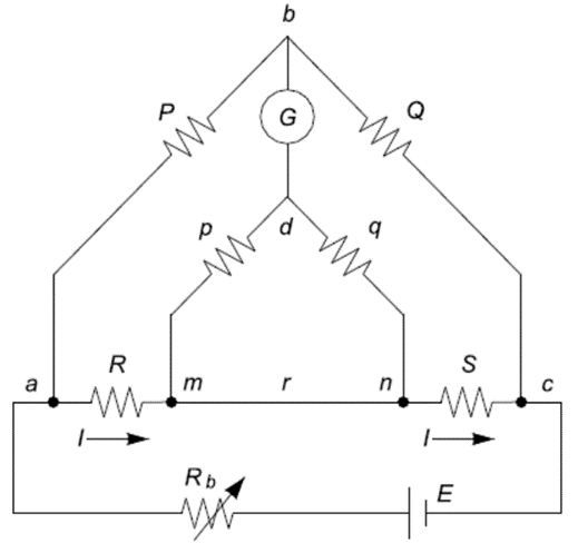
The operation of the Kelvin Bridge is very similar to the Wheatstone bridge except that it is complicated by the presence of two additional resistors; Resistors P and Q are connected to the outside potential terminals of the four terminal known or standard resistor S and the unknown resistor R. The resistors S, R, P and Q are essentially a Wheatstone bridge. In this arrangement, the parasitic resistance of the upper part of S and the lower part of R is outside of the potential measuring part of the bridge and therefore are not included in the measurement. However, the link ‘r’ between S and R is included in the potential measurement part of the circuit and therefore can affect the accuracy of the result. To overcome this, a second pair of resistors ‘p’ and ‘q’ form a second pair of arms of the bridge (hence ‘double bridge’) and are connected to the inner potential terminals of S and R. The detector D is connected between the junction of P and Q and the junction of p and q.
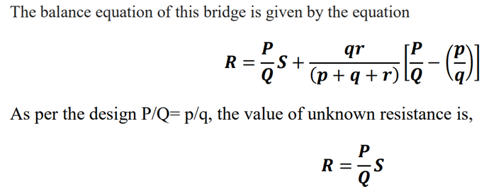
Above equation is the usual working equation for the Kelvin double bridge. It indicates that the resistance of connecting lead ‘r’ has no effect on the measurement provided that the two sets of ratio arms have equal ratios. The above equation is useful however as it shows the error that is introduced in case the ratios are not exactly equal. It is indicated that it is desirable to keep ‘r’ as small as possible in order to minimize the errors in case there is a difference between ratios P / Q and p/q. In a typical Kelvin bridge, the range of resistance calculated is 0.1Ω to 1.0 Ω.
Circuit Diagram:
Procedure:
- Connections are made as per the connection diagram
- Connect the unknown resistance at R terminals.
- Switch ON the unit.
- Select the range selection switch at the point where the meter reads least possible value of voltage.
- Vary the potentiometer (S) to obtain null balance.
- Switch OFF the unit and find the resistance using multimeter at S.
- Tabulate the readings and find the value of unknown resistance using the above formula.
- Repeat the above for different values of unknown resistors.
Observation Table:
| Sl. No. | P (Ω) | Q (Ω) | R (Ω) | S (Ω) | Measured value of unknown Resistor using Multimeter (Ω) |
Apparatus Used:
| Sl No. | Name of Apparatus | Quantity | Specification | Makers name |
| 1. | Kelvin’s Double Bridge Trainer Kit | 1 | Akademika |
Remarks:
Views: 233