Experiment No.: 1
Experiment Name: Study on different types of Water Turbines used in large hydro power plant
Objective:
- To study Kaplan Turbine
- To study Francis Turbine
- To study Pelton Wheel Turbine
Theory:
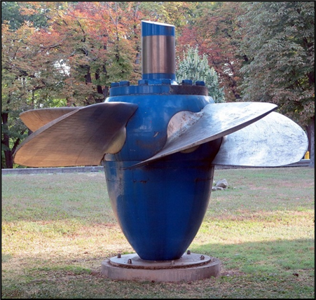
- Kaplan Turbine:
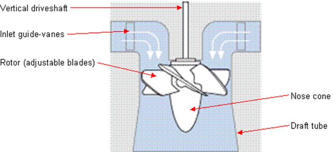
Kaplan Turbine works on the principle of axial flow reaction. In axial flow turbines, the water flows through the runner along the direction parallel to the axis of rotation of the runner. The water at the inlet of the turbine possesses both kinetic energy as well as pressure energy for effective rotation the blades in a hydro-power station.
Different parts of Kaplan Turbine as follows,
1.Scroll casing, 2. Guide Vane Mechanism, 3. Draft Tube, 4. Runner Blades
Working of Kaplan Turbine:
The water coming from the pen-stock is made to enter the scroll casing. The scroll casing is made in the required shape that the flow pressure is not lost. The guide vanes direct the water to the runner blades. The vanes are adjustable and can adjust itself according to the requirement of flow rate. The water takes a 90 degree turn, so the direction of the water is axial to that of runner blades.
The runner blades start to rotate as the water strikes due to reaction force of the water. The runner blades has twist along its length in order to have always optimum angle of attack for all cross section of blades to achieve greater efficiency. From the runner blades, the water enters into the draft tube where its pressure energy and kinetic energy decreases. Kinetic energy is gets converted into pressure energy results in increased pressure of the water. The rotation of the turbine is used to rotate the shaft of generator for electricity production.
Pictorial Representation:
- Francis Turbine:
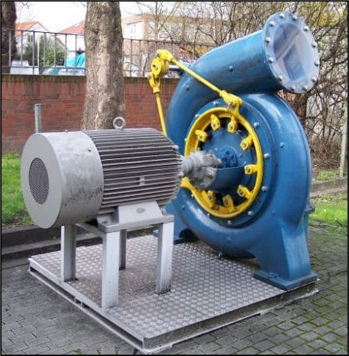
Francis Turbine is a combination of both impulse and reaction turbine, where the blades rotate using both reaction and impulse force of water flowing through them producing electricity more efficiently. Francis turbine is used for the production of electricity in hydro power stations.
Majorly there are 2 turbines flow patterns on which they work, namely radial and axial flow concepts. An American civil engineer by name, James B. Francis in Lowell, Massachusetts comes up with an idea of combining both impulse and reaction turbine where water enters the turbine radically and exits axially.
The main reason of higher efficiency of Francis turbine lies in the design of blades, these blades rotate using both reaction and impulse force of water flowing through them. Due the use of this type of turbines the main problem faced due to the water head availability is eliminated as the turbine uses both the kinetic and potential energy to produce power. For this, it is also known as Mixed Flow turbine.
Different parts of Francis Turbine as follows,
1.Penstock, 2. Spiral Casing, 3. Guide vanes/Stay vanes, 4. Runner and Runner Blade, 5. Draft Tube
Pictorial Representation:

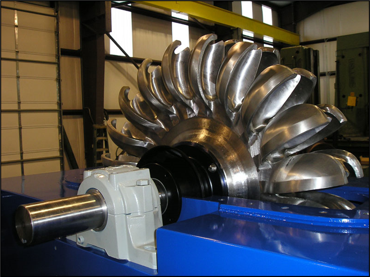
- Pelton Turbine:
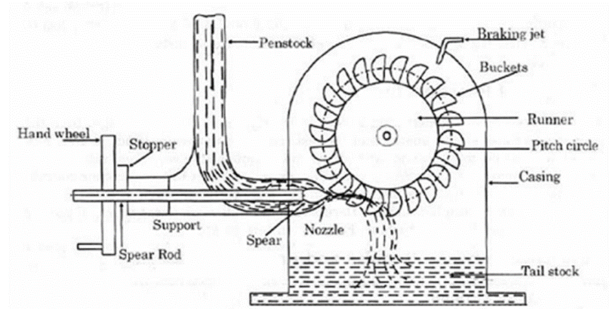
Pelton Turbine is a Tangential flow impulse turbine in which the pressure energy of water is converted into kinetic energy to form high speed water jet and this jet strikes the wheel tangentially to make it rotate. It is also called as Pelton Wheel.
Different parts of Pelton turbine are as follows.
- Nozzle and Flow Regulating Arrangement, 2. Runner and Bucket, 3. Casing, 4. Braking Jet
Working of Pelton Turbine:
- The water is transferred from the high head source through a long conduit called Penstock.
- Nozzle arrangement at the end of penstock helps the water to accelerate and it flows out as a high speed jet with high velocity and discharge at atmospheric pressure.
- The jet will hit the splitter of the buckets which will distribute the jet into two halves of bucket and the wheel starts revolving.
- The kinetic energy of the jet is reduced when it hits the bucket and also due to spherical shape of buckets the directed jet will change its direction and takes U-turn and falls into tail race.
- In general, the inlet angle of jet is in between 1o to 3o, after hitting the buckets the deflected jet angle is in between 165o to 170o.
- The water collected in tail race should not submerge the Pelton wheel in any case.
- To generate more power, two Pelton wheels can be arranged to a single shaft or two water jets can be directed at a time to a single Pelton wheel.
Pictorial Representation:
Views: 101
Pingback: Identify the Routine Maintenance Parts of the Large Hydro Power Plant - Free Electrical Notebook - Theory and Practical