Experiment No.: 4
Experiment Name:
Making & Testing the Control and Power Circuit for Jogging Operation, Forward & Reverse Rotation of Sq. Cage Induction Motor Using Contactor Control.
Objective:
To make & test the control and power circuit for Jogging operation, forward & reverse rotation of
Sq.cage induction motor using contactor control.
Circuit Diagram:
Making the Circuit:
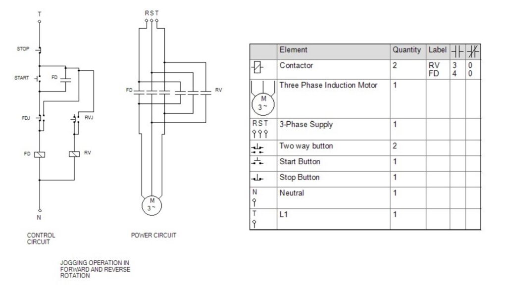
Control Circuit:
- A start push button switch (NO) (START) is connected in series with stop push button switch (NC) (STOP) and an NC contact of a two way switch, FDJ. This is connected in series with a contactor, FD. This whole series combination is connected across any of three phase and neutral.
- A NO contact of contactor, FD is connected acoss the START switch.
- The NO contacts of FDJ is connected after STOP switch and before FD contactor.
- Another two way switch, RVJ and another contactor RV is connected as same as above.
Power Circuit:
- Three phase supply, RST is connected with Squirrel Cage Induction Motor through NO triple contact of contactor, FD.
- A set of NO triple contact of contactor RV is connected across the three phase supply and induction motor by interchanging any two phase connection as shown in diagram.
Operation:
- There may be three kinds of running of the motor. (a) Normal forward starting and continuous running in forward rotation, (b) Jogging in forward rotation and (c) Jogging in reverse rotation.
- (a) To run the motor continuously, only START push button switch is to be pressed and released.
- To stop the motor only STOP push button is to be pressed.
- (b) To run the motor in Jogging forward condition, the two way switch, FDJ is to be pressed as per required time. Then the power is directly fed to the FD contactor, then NO triple contact of FD is closed and the three phase power is fed to the motor. Thus the motor runs in forward rotation till the FDJ is pressed. When FDJ is released then the motor is stopped.
- (c) To run the motor in Jogging reverse condition, the two way switch, RVJ is to be pressed as per required time. Then the power is directly fed to the RV contactor, then NO triple contact of RV is closed and the three phase power is fed to the motor by interchanging S&T phase among RST 3 phase supply. Thus the motor runs in reverse rotation till the RVJ is pressed. When RVJ is released then the motor is stopped.
Remarks:
The control and power circuit of this connection is made in EKTS softwere and tested successfully.
Related posts:
Control Circuit Operation of Automatic Star-Delta Starter of Induction Motor using PLC
Control Circuit Operation of DOL Starter of Induction Motor Using PLC
Control and Power Circuit for Fully-Automatic Star-Delta Starter Operation of Cage Induction Motor u...
To Make & Test the Working of Single Phase Preventer Using Contactor Control.
Views: 116
You need to be a part of a contest for one of the best blogs on the net. I will highly recommend this blog!