Experiment No.: 6
Experiment Name:
To make & test the control circuit operation of automatic star-delta starter of induction motor using PLC.
Objective:
To simulate the control circuit operation of automatic star-delta starter of induction motor using PLC.
Ladder Diagram:
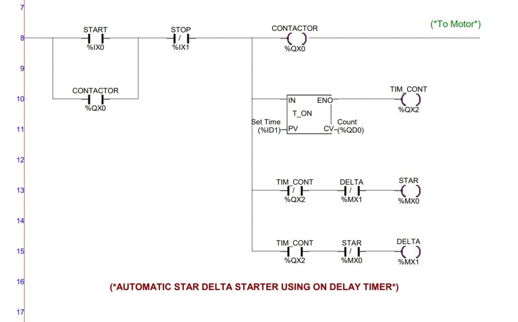
Making the Ladder Diagram:
In the there are only two inputs, i.e. START and STOP and four outpur coils, CONTACTOR, TIM_CONT, STAR and DELTA.
- From ladder line 8, a rung is connected with input NO contact, START push button switch (address %IX0), NC contact, STOP push button switch (address %IX1) and a output coil CONTACTOR (address %QX0) in series. And this combination conncted with Motor. Across the NO START button, a NO contact (address %QX0) of CONTACTOR is conncted.
- Between NC, STOP switch and ouput coil CONTACTOR, a vertical rung is connected with three different horizontal rung.
- 1st horizontal rung is connected with input, IN terminal of an on-delay timer, T-ON. The enable output termainal, ENO is connected with an output coil, TIM_CONT (address %QX2). The addresses are defined in the preset value, PV and count value, CV terminal of T-ON. The variable input preset value is to be set during simulation.
- The second horizontal rung is connected with NC contact of output coil, TIM_CONT and the NC contact of output coil, DELTA in series with an output coil, STAR.
- The third horizontal rung is connected with NO contact of TIM_CONT and the NC contact of output coil STAR is series with an output coil, DELTA.
Observation:
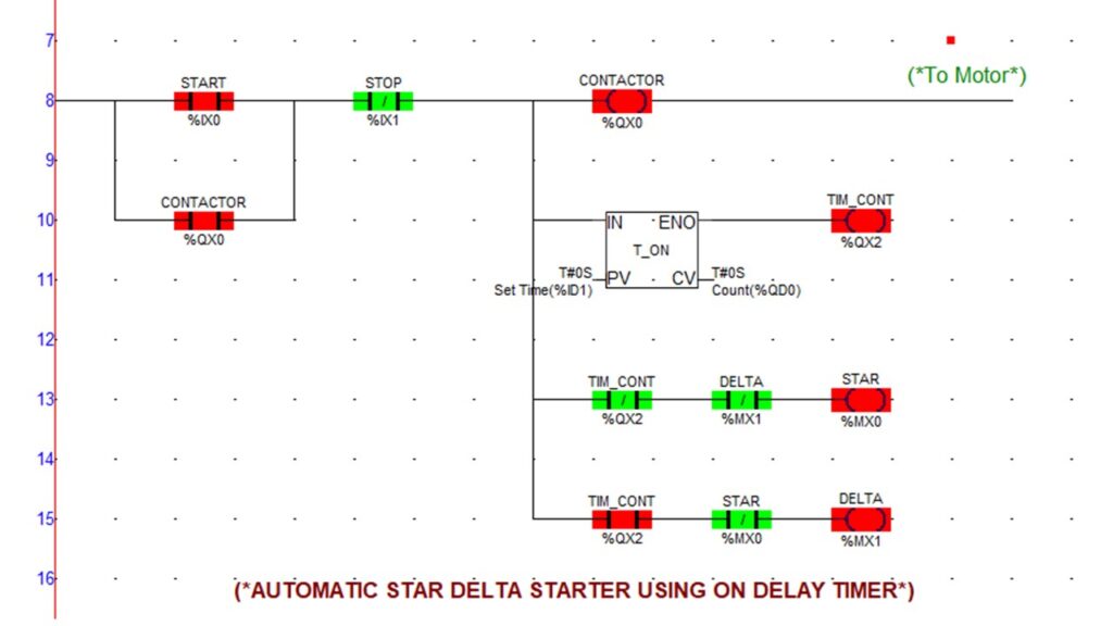
Condition : 1 – When the motor is in OFF condition.
| START (Input) | STOP (Input) | CONTACTOR (Output : Motor) | On-delay Timer | TIM_CONT (Timer Output Coil) | STAR (Output coil) | DELTA (Output coil) | TIM_CONT (NC contact) | TIM_CONT (NO contact) | DELTA (NC contact) | STAR (NC contact) |
| 0 | 0 | 0 | Not Set | 0 | 0 | 0 | 0 | 0 | 0 | 0 |
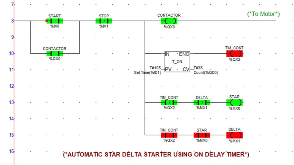
Next, the preset value (PV) of the on-delay timer, T-ON is set to 10 sec.
Condition : 2 – The START switch is pressed ON then motor is started in star connected condition. The on-delay timer started countdown upto preset value.
| START (Input) | STOP (Input) | CONTACTOR (Output : Motor) | On-delay Timer | TIM_CONT (Timer Output Coil) | STAR (Output coil) | DELTA (Output coil) | TIM_CONT (NC contact) | TIM_CONT (NO contact) | DELTA (NC contact) | STAR (NC contact) |
| 1 | 0 | 1 | 10 sec 0D0H0M10S0MS | 0 | 1 | 0 | 0 | 0 | 0 | 1 |
Condition : 3 – After countdown is over, the NC contact of the timer, TIM_CONT, get opened and NO contact of the timer is closed. As a result, the STAR output coil is de-energised and DELTA output coil is energised at the same instant by interchanging the condition of the NC contacts of DELTA & STAR coils. And thus, the motor switched to delta connected position and continues to run in delta connection.

| START (Input) | STOP (Input) | CONTACTOR (Output : Motor) | On-delay Timer | TIM_CONT (Timer Output Coil) | STAR (Output coil) | DELTA (Output coil) | TIM_CONT (NC contact) | TIM_CONT (NO contact) | DELTA (NC contact) | STAR (NC contact) |
| 1 | 0 | 1 | Count down done 0D0H0M0S0MS | 1 | 0 | 1 | 1 | 1 | 1 | 1 |
Condition : 4 – When the STOP switch is pressed ON, then motor turned OFF.

| START (Input) | STOP (Input) | CONTACTOR (Output : Motor) | On-delay Timer | TIM_CONT (Timer Output Coil) | STAR (Output coil) | DELTA (Output coil) | TIM_CONT (NC contact) | TIM_CONT (NO contact) | DELTA (NC contact) | STAR (NC contact) |
| 0 | 1 | 0 | Not Set | 0 | 0 | 0 | 0 | 0 | 0 | 0 |
Before starting again the motor, at first the START switch is to be turned OFF and then STOP switch is turned OFF. Now the motor is ready to start again.
Remarks:
This ladder logic program is compiled and simulated on the softwere, SELPRO v.5.3.6. successfully.
Views: 243
You need to be a part of a contest for one of the best blogs on the net. I will highly recommend this blog!