Experiment No.: 1
Experiment Name:
Identification of different parts (along with function and materials) for a given three phase induction motor.
Objective:
To identify (i) different parts (ii) function and (iii) materials of a three phase induction motor.
Theory:
The three phase induction motor is the most widely used electrical motor. Almost 80% of the mechanical power used by industries is provided by 3 ph induction motor because of its simple and rugged in construction, low cost, good operating characteristics. In three phase induction motor, the power is transferred from stator to rotor winding through induction. The induction motor is also called asynchronous motor as it runs at a speed other than the synchronous speed.
Stator Parts:
| Sl. No. | Stator Parts | Position | Function | Materials |
| 1. | Yoke | Outer part of Induction Motor | To hold the stator core and 3 phase windings | Cast iron |
| 2. | Stator core | Fitted inner part of the yoke | To hold the windings | Laminated Silicon steel |
| 3. | 3 phase windings | 3 different windings short pitched or full pitched and connected in star or delta connection | To produce uniform rotating magnetic field | Copper with Class B insulation |
| 4. | Terminal Box | Mounted on the surface of the yoke | To cover the connecting terminals | Mild steel |
| 6. | Name Plate | Reveted on the surface of yoke | To show the details of the motor, i.e. power in HP, voltage, full load current, full load speed in rpm, frequency, bearing number, duty cycle, insulation class, serial number, manufactures details etc. | Aluminium |
| 7. | Cooling Fins | Casted with yoke | To increase the surface area of the yoke for cooling purpose by circulating air | Cast Iron |
| 8. | End covers (Front & rear) | Fitted with yoke by bolt, on the front side and rear side of the motor | To hold the bearings and to protect the motor by covering the faces | Cast Iron |
| 9. | Bearing housing | Casted with end covers or separately fitted | To hold the bearings | Cast Iron |
| 10. | Bolts & Screwes | Fitting the loose parts of the motor | To fit the end covers and terminals box with yoke | Mild steel |
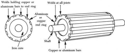
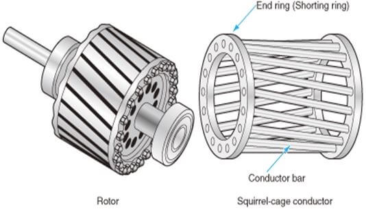
Rotor Parts:
| Sl. No. | Rotor Parts | Position | Function | Materials |
| 1. | Shaft | Placed on the bearings | To couple mechanical load with the motor | Carbon steel |
| 2. | Rotor core | Mounted on the Shaft | To hold the aluminium rotor bars and end rings | Laminted Silicon Steel |
| 2. | Rotor aluminium bars | Fitted on the surface of the rotor core by skewing | To produce rotor emf, current and field. Behaves like a shorted secondary winding. | Aluminium |
| 3. | Aluminium end rings | Mounted on two side of the core | To short the rotor bars and create a closed path for conducting the rotor current | Aluminium |
| 4. | Bearings | Placed inside the bearing housing of stator end covers | To help the shaft for rotation of the rotor inside the stator by reducing the friction | Chrome Steel |
| 5. | Fan | Fitted on the shaft | To cool the motor by forcing natural air. | Mild steel or Aluminium |
Diagram:


Apparatus Used:
| Sl No. | Name of Apparatus | Specification | Quantity | Makers name |
| 1. | 3 ph Squirrel Cage Induction Motor | 1 HP, 415V, 50 Hz,1440 rpm | 1 | Tech-Track |
Remarks: All parts of the three phase induction motor is dismantled and assembled successfully.
Related posts:
Direct Load Test on the 3-ph Squirrel Cage Induction Motor and Plotting the i) Efficiency Versus Out...
Direct Loading Test on 3-ph Alternator to Determine the Regulation and Efficiency
No-load Test on 3-ph Squirrel Cage Induction Motor and Determine the Equivalent Circuit Parameters
Measure the Open Circuit Voltage Ratio of the 3-ph Slip Ring Induction Motor
Views: 4145
You need to be a part of a contest for one of the best blogs on the net. I will highly recommend this blog!