Experiment No.: 2
Experiment Name:
Perform the Direct Load Test on the Three Phase Squirrel Cage Induction Motor and Plot the i) Efficiency Versus Output, ii) Power Factor Versus Output, iii) Power Factor Versus Motor Current and iv)Torque – Slip/Speed Characteristics
Objective:
- (a) To perform direct load test on the three phase squirrel cage induction motor.
- (b) To plot (i) Efficiency Versus Output, (ii) Power Factor Versus Output, (iii) Power Factor Versus Motor Current, (iv) Torque – Slip Characteristics, (v) Torque – Speed Characteristics.
Theory:
The load test on induction motor is performed to compute its complete performance i.e. torque, slip, efficiency, power factor etc. During this test, the motor is operated at rated voltage and frequency and normally loaded mechanically by brake and pulley arrangement from the observed data, the performance can be calculated, following the steps given below.
- Slip: The speed of rotor, Nr droops slightly as the load on the motor is increased. The synchronous speed, Ns of the rotating magnetic field is calculated, based on the number of poles, P and the supply frequency, f i.e

Then, load torque, T = (W × d/2) kg-m
= (W × d/2 × 9.81) N-m [where, d = effective diameter of the brake drum in meters]
Output = Torque × Speed
Thus as the speed of motor does not vary appreciably with load torque will increase with increasing load.
Net force exerted, W = (S1 – S2) kg
Then, load torque, T = (W × d/2) kg-m = (W × d/2 × 9.81) N-m [where, d = effective diameter of the brake drum in meters]
- Output Power, PO: The output power in watts developed by the motor is given by, PO = 2πNT/60 [where, N is the speed of the motor in r. p. m]
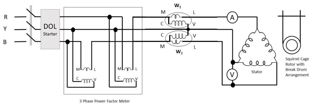
- Input Power: Input power is measured by the two wattmeters, properly connected in the circuit i.e. Input power = (W1 + W2) watts [where, W1 and W2 are the readings of the two wattmeters]. If the pointer of any of the wattmeter deflects -ve value then it should be subtracted from the value of another wattmeter.
- Power Factor: Power factor of induction motor on NO-LOAD is very low because of the high value of magnetising current. With the increase in load the power factor increases because the power component of the current is increased. Low power factor operation is one of the disadvantages of induction motor. An induction motor draws heavy amount of magnetising current due to presence of air gap between the stator and rotor. Thus to reduce the magnetising current in induction motor the air-gap is kept as small is possible.
Input power factor is directly measured by using 3ph power factor meter. It may be noted clearly at this stage, that the power factor of the induction motor is very low at no load, hardly 0.1 to 0.25 lagging.
- Efficiency:

Full load efficiency of 3 phase induction motor lies in the range of 72 % (for small motors) to 82 % (for very large motors).
- Speed: When the induction motor is on NO-LOAD speed is slightly below the synchronous speed. The current due to induced emf in the rotor winding is responsible for production of torque required at NO-LOAD. As the load is increased the rotor speed is slightly reduced. The emf induced in the rotor causes the current increased to produce higher torque, untill the torque developed is equal to torque required by load on motor.
Circuit Diagram :

Observation Table : Constant Value taken:
- Gravitational acceleration (g) = 9.81 m/s2
- Synchronous Speed (Ns) = 1500 rpm
- Radius of the brake drum (r) = 50 mm = 50×10-3 m
| Sl. No. | Line Voltage (VL) (V) | Line Current (IL) (A) | Power Factor (cosφ) | W1 (Watt) | W2 (Watt) | (W1+W2 )x4 (M.F.=4) (Watt) | S1 (kg) | S2 (kg) | S1~S2 (kg) | Rotor Speed (N) (rpm) | %Slip = (Ns-N)/Ns x 100% | Calculated Torque [T = (S1-S2).g)x r] (N-m) | Calculated Output Power [Pout = (2𝜋N.T)/60] (W) | Efficiency (η = Pout/Pin) x 100% |
| 1. | 402.5 | 0.96 | 0.3 | -25 | 70 | 45×4=180 | 0 | 0 | 0 | 1493 | 0.46% | |||
| 2. | 402.5 | 1.00 | 0.35 | -10 | 90 | 80×4=320 | 3 | 0 | 3 | 1485 | 1.0% | 1.4 | 217.71 | 68.03% |
| 3. | 402.2 | 1.07 | 0.49 | 0 | 105 | 105×4=420 | 5 | 0 | 5 | 1481 | 1.26% | 2.45 | 379.97 | 90.46% |
| 4. | 399.2 | 1.12 | 0.58 | 15 | 120 | 135×4=540 | 7 | 0 | 7 | 1460 | 2.66% | 3.43 | 524.41 | 97.11% |
| 5. | 398.5 | 1.27 | 0.63 | 40 | 145 | 185×4=740 | 8.5 | 0 | 8.5 | 1456 | 2.93% | 4.16 | 634.28 | 85.71% |
| 6. | 397.9 | 1.39 | 0.68 | 50 | 155 | 205×4=820 | 10 | 0 | 10 | 1450 | 3.33% | 4.90 | 744.03 | 90.73% |
| 7. | 398.0 | 1.5 | 0.71 | 60 | 175 | 235×4=940 | 12.5 | 0 | 12.5 | 1441 | 3.39% | 6.13 | 925.02 | 98.40% |
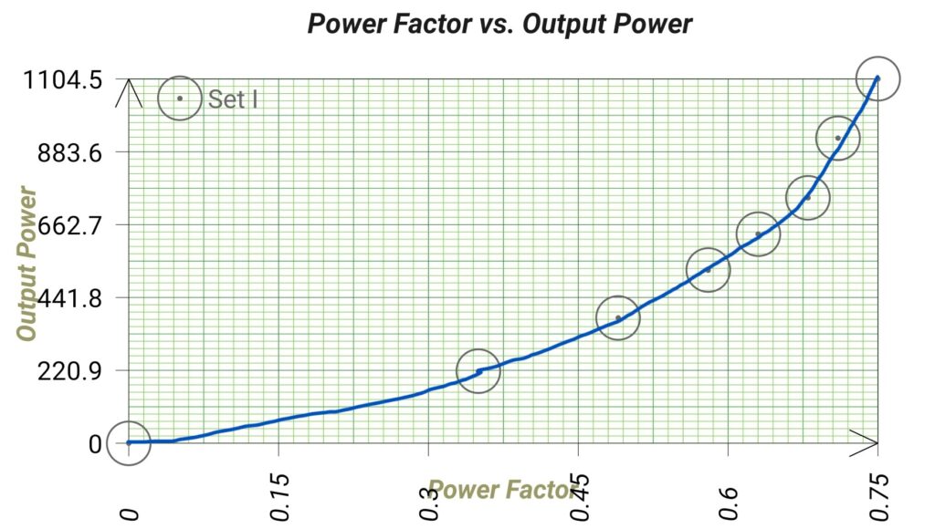
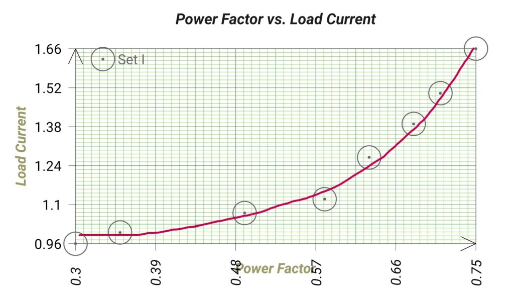
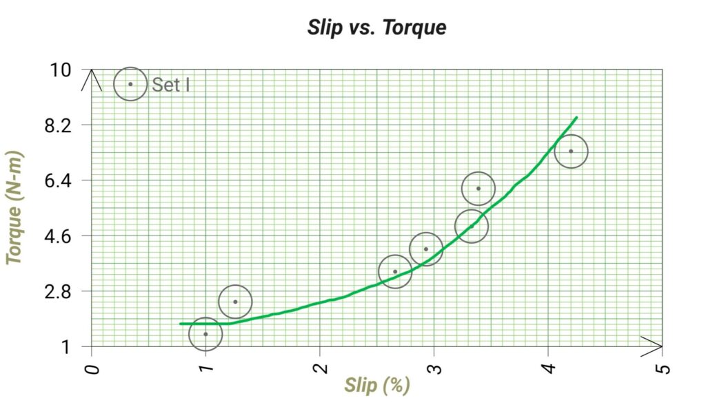
| 8. | 396.7 | 1.66 | 0.75 | 90 | 190 | 280×4=1120 | 15 | 0 | 15 | 1437 | 4.2% | 7.34 | 1104.54 | 98.61% |
Calculation:
Calculated Input Power, (Pin= W1+W2). If the pointer of any of the wattmeter deflects -ve value then it should be subtracted from the value of another wattmeter. The negetive value indicates the power factor of the load is lagging.
%Slip = (Ns-N)/Ns x 100%
%Slip = ((1500-1485)/1500) x100% = 1.0%
Calculated Torque, T = (S1-S2).g)x r
T=(3-0)x9.81×0.05 = 1.4 N-m
Calculated Output Power, Pout = (2𝜋N.T)/60
Pout= (2𝜋 x 1485 x 1.4)/60 = 217.71 W
Efficiency, η = (Pout/Pin) x 100%
η = (217.71/320)x100 = 68.03%
Graph:


Apparatus Used:
| Sl No. | Name of Apparatus | Specification | Quantity | Makers name |
| 1. | 3 ph Squirrel Cage Induction Motor | 2 HP, 415V, 50 Hz, 3 A, 1440 rpm with brake drum. | 1 | M.E.W. |
| 2. | Clampmeter | 0-200A AC | 1 | Metravi |
| 3. | Digital Multimeter as Voltmeter | 0-750 V AC, 0-1000 V DC, 0-10 A | 1 | Akademika |
| 4. | 3 ph Power Factor Meter | 0.5 lead – 1 – 0.5 lag, EDM type | 1 | Automatic Electric Limited |
| 5. | Digital Tachometer | Non contact type | 1 | Metrix+ |
| 6. | Spring Balance | 0-50 kg | 2 | Prince |
| 7. | Single phase Wattmeter | 0-750-1500-3000 W, 0-150-300-600 V, 0-5-10 A, | 2 | MECO-G |
Remarks: We observed that with increasing the load, the power factor of the motor is improving from 0.3 lag to 0.8 lag, the speed of the motor is decreasing and slip of the motor is increasing. When the brake drum belt is tightened then enormous heat is produced in the drum, so we have to pour water into the drum for cooling purpose.
