Experiment No.: 3
Experiment Name:
No-load Test on 3-ph Squirrel Cage Induction Motor and Determine the Equivalent Circuit Parameters.
Objectives:
- To conduct no-load test on 3-ph Squirrel Cage Induction Motor
- To determine the equivalent circuit parameters
Theory:
In the no load test, the machine is run at no load, the slip is then quite small and hence the total rotor resistance (R2’ / s) becomes quite large Due to this: we can ignore the rotor current I2’ and say that the rotor (i.e. the secondary side of the machine) is open circuited. The motor is operated at the rated voltage and the stator current, voltage, and power input are noted. Let the per phase values of these quantities be I0, V1, and P0, respectively. Out of P0, let the core losses be Pi, Thus, the approximate equivalent circuit then becomes as shown in the figure below, for the no load condition.
In this, it is true that the current Io flows through the stator impedance (R1+jX1), but since the no load current is quite small, the equivalent circuit in the figure above is acceptable. Thus from this equivalent circuit.
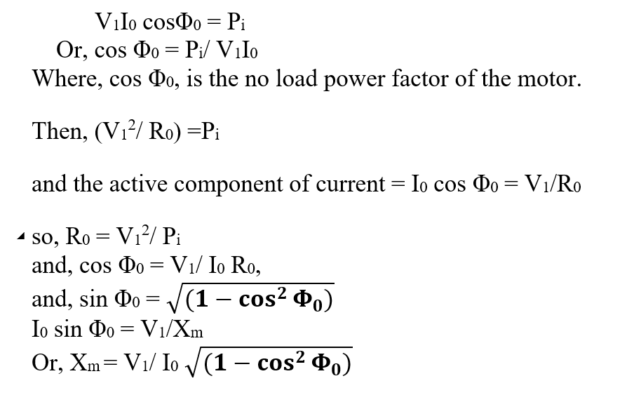
Thus, with the three observations during the no load test, the two parameters R0 and Xm are calculated.
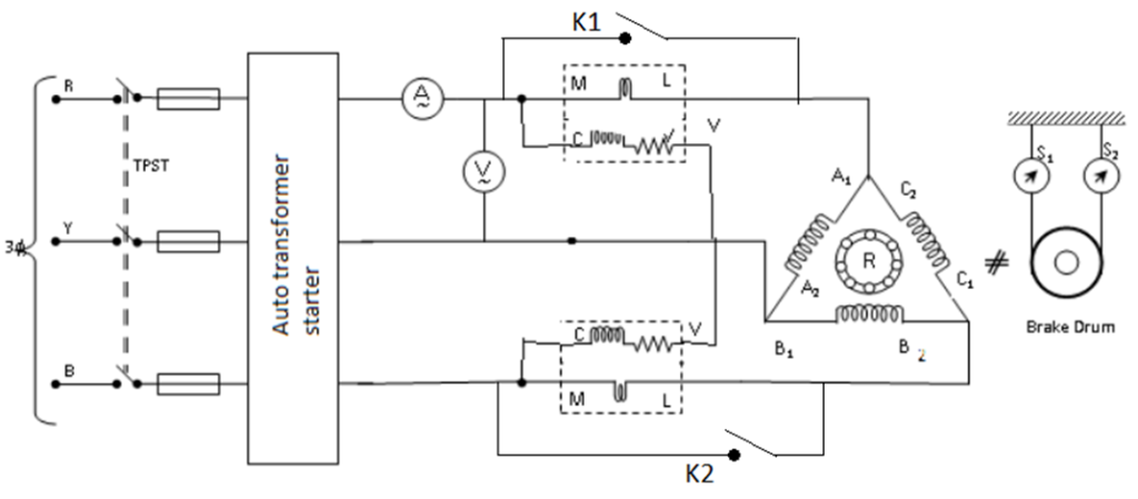
The two short circuiting keys K, and K, are to be closed while starting the motor. After the motor runs at normal speed, the keys are opened. This is necessary to avoid any damage to the low current ammeters and current-coils due to the heavy currents during starting.
Circuit Diagram:
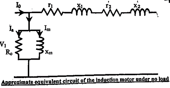
Equivalent Circuit of Induction Motor under No Load:
Observation Table:
| Sl. No. | Voltage (V1) | Line Current (I0) | Phase Current (I0) | W1 | W2 | W1+W2 x M.F | cos φ = (W1+W2)/√3.V1.I0 | sin φ = sin (cos-1 φ) | Iw = I0 cos φ | Iμ = I0 sin φ | R0 per phase = V1/Iw | Xm per phase= V1/Iμ |
| Unit | Volt | Amp | Amp | Watt | Watt | Watt | Amp | Amp | Ω | Ω | ||
| 1. | 401.2 | 1.07 | 0.617 | -50 | 70 | 70-50= 20×4 = 80 | 0.107 | 0.994 | 0.066 | 0.613 | 3509.6 | 377.87 |
| 2. | 397.5 | 1.08 | 0.623 | -50 | 70 | 80 | 0.107 | 0.994 | 0.066 | 0.619 | 3477.22 | 370.75 |
Calculation: as per data in serial no. 1 in observation table:
Iw = I0 cos φ = 0.617×0.107 = 0.066 A
sin φ = sin (cos-1φ) = sin 83.86 = 0.994
Iμ = I0 sin φ = 0.617×0.994 = 0.613 A
R0 per phase = V1/Iw = (401.2/√3)/0.066 = 3509.6 Ω
Xm per phase= V1/Iμ = (401.2/√3)/0.613 = 377.87 Ω
Apparatus Used:
| Sl No. | Name of Apparatus | Specification | Quantity | Makers name |
| 1. | 3 ph Squirrel Cage Induction Motor | 2 HP, 415V, 50 Hz, 3 A, 1440 rpm with brake drum. | 1 | M.E.W. |
| 2. | Clampmeter | 0-200A AC | 1 | Metravi |
| 3. | Digital Multimeter as Voltmeter | 0-750 V AC, 0-1000 V DC, 0-10 A | 1 | Akademika |
| 4. | Digital Tachometer | Non contact type | 1 | Metrix+ |
| 5. | Single phase Wattmeter | 0-750-1500-3000 W, 0-150-300-600 V, 0-5-10 A, | 2 | MECO-G |
Remarks:
Related posts:
Direct Load Test on the 3-ph Squirrel Cage Induction Motor and Plotting the i) Efficiency Versus Out...
Measure the Open Circuit Voltage Ratio of the 3-ph Slip Ring Induction Motor
Identification of Different Parts for a Three Phase Induction Motor (along with Function and Materia...
Determine the Regulation and Efficiency of 3 ph Alternator from OC and SC Tests (Synchronous impeda...
Views: 2208