Experiment No.: 7
Experiment Name:
Determine the regulation and efficiency of the given three phase alternator from OC and SC tests (Synchronous impedance method)
Objective:
- To perform open circuit test on three phase alternator
- To perform short circuit test on three phase alternator
- To determine the regulation of that alternator
- To determine the efficiency of that alternator
Theory:
The synchronous impedance method or EMF method is used to determine the voltage regulation of the larger alternators. The synchronous impedance method is based on the concept of replacing the effect of armature reaction by an imaginary reactance.
For an alternator, V= Ea−Ia Zs= Ea−Ia(Ra+jXs)—————(1)
At first, the synchronous impedance (𝑍𝑠) is measured and then, the value of actual generated EMF (𝐸a) is calculated. Thus, from the values of (𝐸a) and V, the voltage regulation of the alternator can be calculated.
Measurement of Synchronous Impedance:
In order to determine the value of synchronous impedance, following tests are performed on an alternator −
- DC Resistance Test
- Open-Circuit Test
- Short-Circuit Test
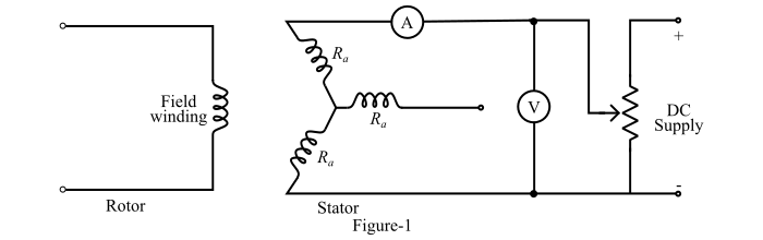
DC Resistance Test:
Consider the alternator is star-connected with the field winding open-circuited. Now, measure the DC resistance between each pair of terminals either by using Wheatstone’s bridge or ammeter-voltmeter method. The average of three sets of resistance values Rt is taken. This value of Rt is divided by 2 to obtain the DC resistance per phase.
While performing the test, the alternator should be at rest, because the AC effective resistance is greater than DC resistance due to skin effect. The AC effective resistance per phase may be obtained by multiplying the DC resistance by a factor 1.20 to 1.75 depending upon the size of the alternator.
Circuit Diagram for the DC resistance test:
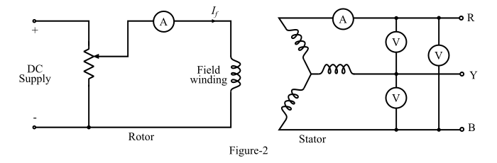
Open-Circuit Test:
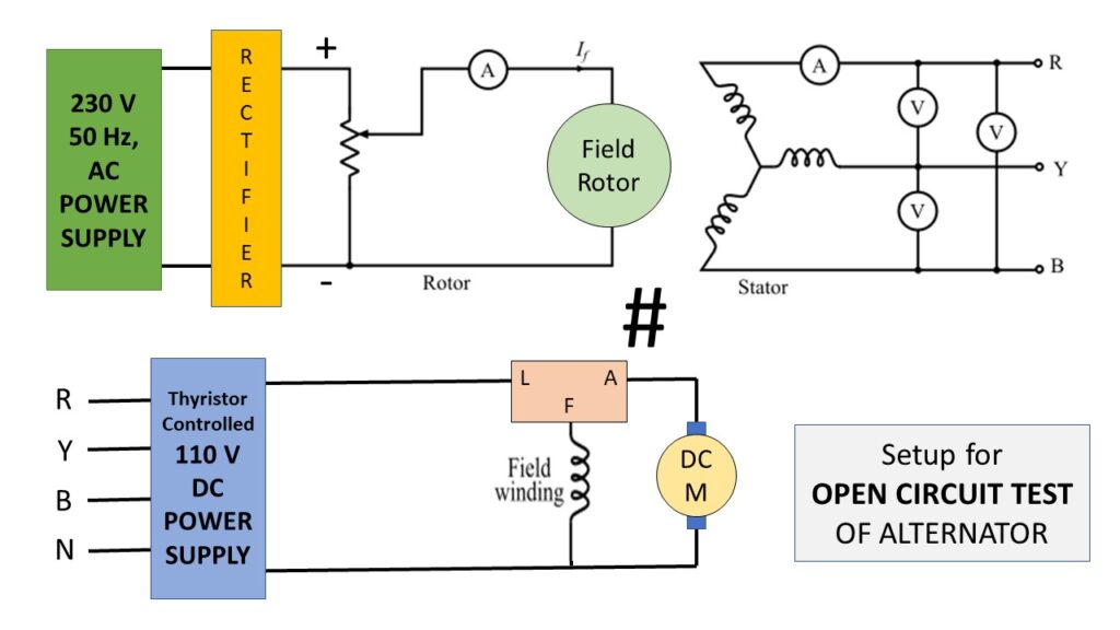
To perform the open-circuit test, the load terminals are kept open and the alternator is run at rated synchronous speed. The circuit diagram of the open-circuit test is shown in Figure-2.
Initially, the field current is set to zero. Then, the field current is gradually increased in steps and the open-circuit terminal voltage Et is measured in each step. The field current may be increased to obtain 25 % more than rated voltage of the alternator.
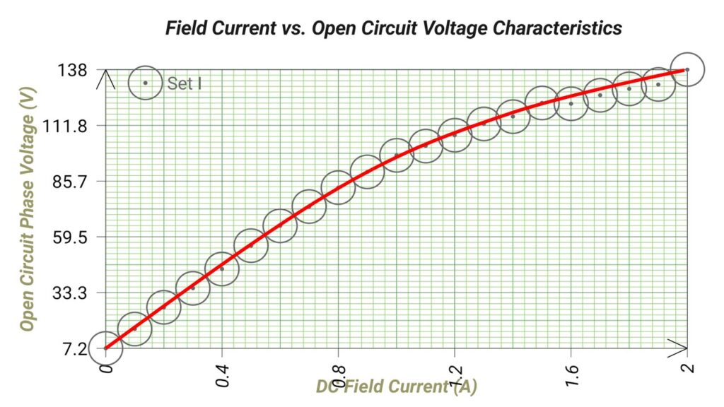
A graph is plotted between the open-circuit phase voltage (Eph=Eline/√3) and the field current (𝐼𝑓). The obtained characteristic curve is known as open-circuit characteristic (O.C.C) of the alternator (Figure-3).

The shape of O.C.C. is same as a normal magnetisation curve. When the linear portion of the O.C.C. is extended, it given the air-gap line of the characteristic.
Circuit Diagram for Open Circuit Test:
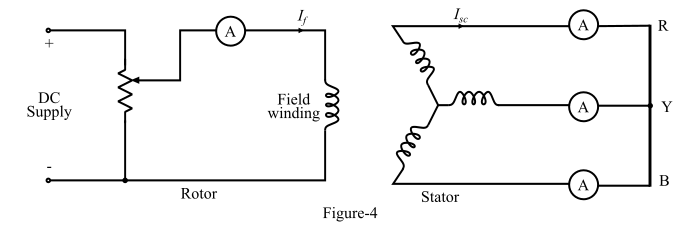
Short-Circuit Test:
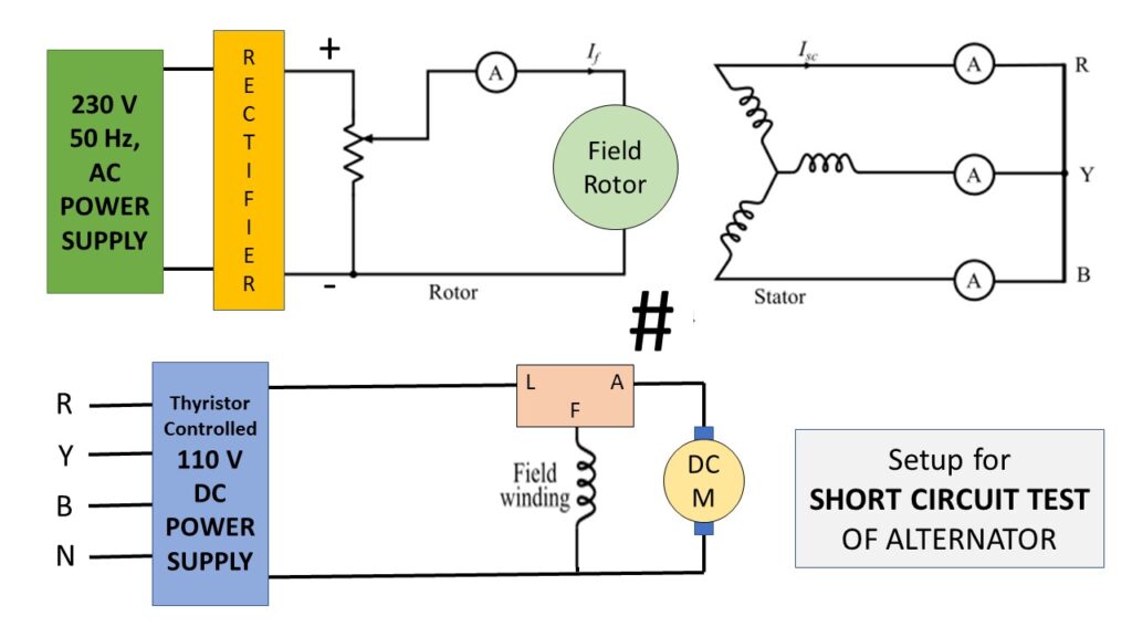
For performing the short-circuit test, the armature terminals are short-circuited through three ammeters as shown in Figure-4.
Before starting the alternator, the field current should be decreased to zero. Each ammeter should have a range more than the rated full-load value. Now, the alternator is run at synchronous speed. Then, the field current is gradually increased in steps and the armature current is measured at each step. The field current may be increased to obtain the armature currents up to 150 % of the rated value.
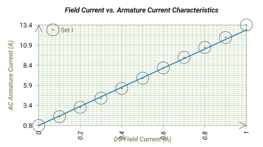
The field current (𝐼𝑓) and the average of the three ammeter readings is taken at each step. A graph is plotted between the armature current (𝐼a) and the field current (𝐼𝑓). The obtained characteristic is known as short-circuit characteristic (S.C.C.) of the alternator and this characteristic is a straight line as shown in Figure-5.

Circuit Diagram for Short Circuit Test:
Calculation of Synchronous Impedance (𝒁𝒔):
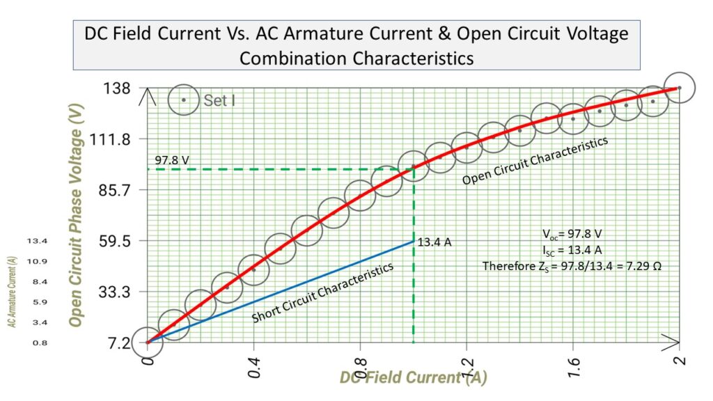
In order to calculate the synchronous impedance of the alternator, the O.C.C. and the S.C.C. are drawn on the same curve sheet, as shown in Figure-6.

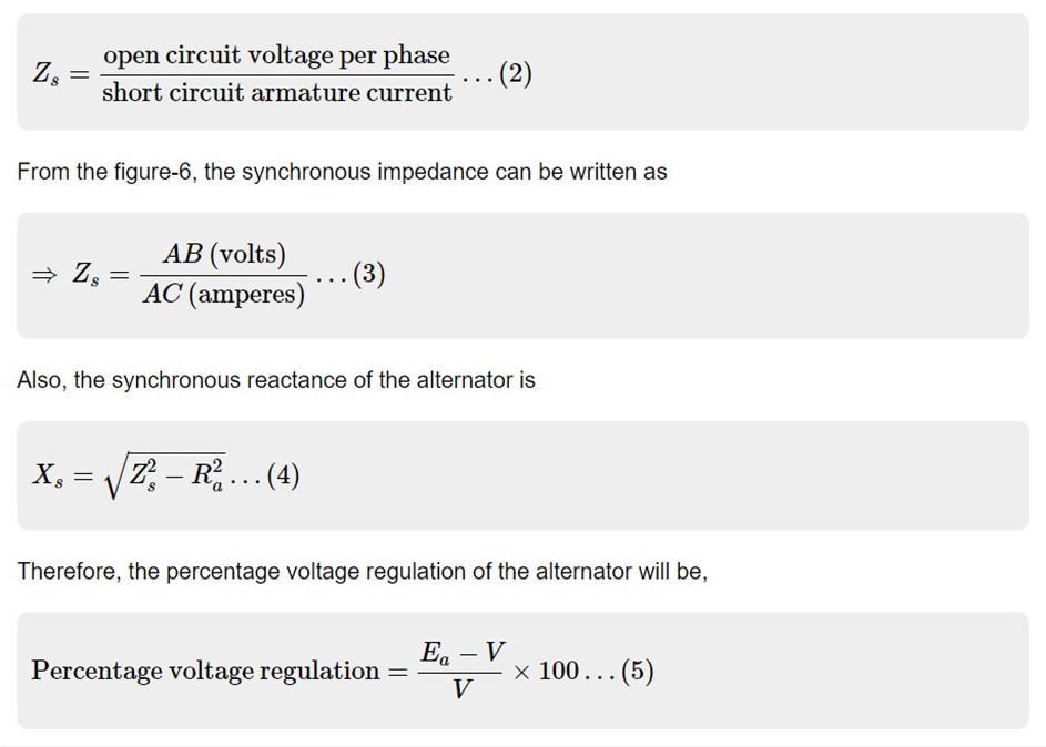
Then, determine the value of short-circuit current (𝐼𝑆𝐶) at the field current that gives the rated voltage per phase of the alternator. The synchronous impedance (𝑍𝑠) will then be equal to the ratio of the open-circuit voltage to the short-circuit current at the field current which gives the rated voltage per phase, i.e.,
Circuit Diagram:
Experimental Setup for Open Circuit Test:
Experimental Setup for Short Circuit Test:
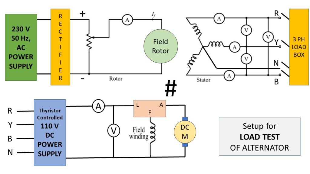
Experimental Setup for Load Test:
Observation Table:
Resistance Test:
| Sl. No. | RRY (Ω) | RYB (Ω) | RBR (Ω) | Avarage Resitance (Rt)(Ω) | DC Resistance Per Phase (Rt/2) (Ω) | AC Resistance Per Phase (Ω) = DC Resistance Per Phase × 1.5 (Ra) (Ω) |
| 1. | 1.78V/1.5A = 1.18 | 2.08V/1.5A = 1.38 | 3.0V/2.6A = 1.15 | 1.24 | 0.62 | 0.93 |
Speed of the Alternator : 1500 rpm
From Open Circuit Test:
| Sl. No. | DC Field Current (If) (A) | Open Circuit Phase Voltage (Eph) (V) |
| 1. | 0 | 7.18 |
| 2. | 0.1 | 16.28 |
| 3. | 0.2 | 26.37 |
| 4. | 0.3 | 35.40 |
| 5. | 0.4 | 44.40 |
| 6. | 0.5 | 55.3 |
| 7. | 0.6 | 64.7 |
| 8. | 0.7 | 73.7 |
| 9. | 0.8 | 82.60 |
| 10. | 0.9 | 90.00 |
| 11. | 1.0 | 97.8 |
| 12. | 1.1 | 102.2 |
| 13. | 1.2 | 107.2 |
| 14. | 1.3 | 112.5 |
| 15. | 1.4 | 116.0 |
| 16. | 1.5 | 122.4 |
| 17. | 1.6 | 122.0 |
| 18. | 1.7 | 126.0 |
| 19. | 1.8 | 129.0 |
| 20. | 1.9 | 131.0 |
| 21. | 2.0 | 138.0 |
From Short Circuit Test:
| Sl. No. | DC Field Current (If) (A) | AC Armature Current (Ia) (A) |
| 1. | 0 | 0.84 |
| 2. | 0.1 | 1.95 |
| 3. | 0.2 | 3.10 |
| 4. | 0.3 | 4.25 |
| 5. | 0.4 | 5.46 |
| 6. | 0.5 | 6.75 |
| 7. | 0.6 | 8.04 |
| 8. | 0.7 | 9.36 |
| 9. | 0.8 | 10.60 |
| 10. | 0.9 | 11.85 |
| 11. | 1.0 | 13.40 |
From Load Test:
| Sl. No. | Input Voltage to the DC Shunt Motor (Vin) (V) | Input Current to the DC Shunt Motor (Iin)(A) | Input Power (Vin×Iin) (W) | Input Field Current to Alternator (If) (A) | Output Voltage per phase at full load (V) | Load Current at full load (A) | Load pf (cos Φ) | Output Power (√3 Vout×Iout×cos Φ) (W) | Efficiency (η) |
| 1. | 108 | 4.1 | 442.8 | 1.9 | 72.22 | 1.31 | unity | 163.86 | 37.00 % |
Graph:
Calculation:
Synchronous impedance of the given alternator is,
Zs = Open circuit voltage / Short circuit armature current = 97.8/13.4 = 7.29 Ω
The synchronous reactance of the alternator is,
Xs = √(Z2s−R2a) = √(7.292−0.932) = 7.23 Ω
The connected load is purely resistive, so power factor is taken as unity. So cos Φ = 1 and sin Φ = 0
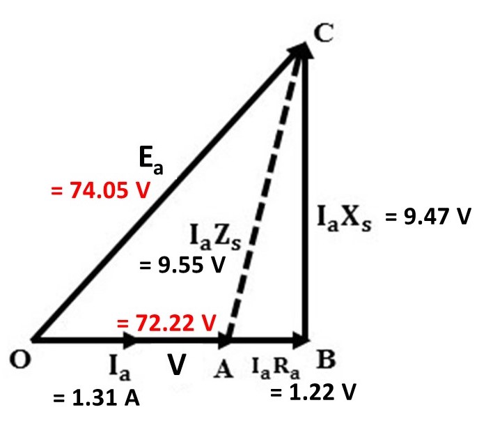
Ea=√((V cos Φ+IaRa)2+(V sin Φ+IaXs)2)
= √(((72.22 ×1)+(1.31×0.93))2+((72.22×0)+(1.31×7.23))2) = 74.05 V
Load Voltage observed (V)= 72.22 V
Percentage voltage regulation Up= (Ea−V)/V×100% = (74.05-72.22)/72.22×100% = 2.53 %
Percentage voltage regulation Down= (Ea−V)/Ea×100% = (74.05-72.22)/74.05×100% = 2.47 %
Efficiency, η = Output power (Pout) / Input Power (Pin) ×100% = 163.86/442.8×100% = 37.00%
Vector Diagram:
Apparatus Used:
| Sl. No. | Name of the Apparatus | Specification | Quantity | Maker’s Name |
| 1. | Alternator | 3-ph, 1500 rpm, 3 kVA, 12.6A, 110V, Field Current: 2A | 1 | Tech-Track |
| 2. | DC Motor | 5HP, 1500 rpm, Shunt Wound, 110V, 40A, Field Current: 2A | 1 | Tech-Track |
| 3. | Thyristor Controlled DC Power Supply | Input: 3-ph, 440V AC Output: 220V, 50A DC | 1 | Sushama Electronics |
| 4. | Tachometer | Digital, Non-contact type, 2.5-99999 rpm | 1 | Metrix+ |
| 5. | Clip-on Ammeter | 0-1000A AC | 1 | Metravi |
| 6. | Digital Multimeter | 0-750V, 0-10A AC | 1 | Akademika |
| 7. | Resistive Load Box | 15A, 220 V | 1 | Tech-Track |
Remarks: Performing all test we have successfully find out the all parameters regarding the vector diagram. We have find out the regulation and efficiency of the alternator succesfully.
Views: 2043