Experiment No: 4
Experiment Name:
Testing of Percentage Differential Protection of Transformer using Electromagnetic Type Transformer Differential Relay.
Objective:
- To test Percentage Differential Protection of Transformer using electromagnetic type Transformer Differential Relay.
- To plot a graph between relay operating current and tripping time.
Theory:
Principle of Differential Protection scheme is one simple conceptual technique. The differential relay actually compares between primary current and secondary current of power transformer, if any unbalance found in between primary and secondary currents the relay will actuate and inter trip both the primary and secondary circuit breaker of the transformer.
Suppose we have one transformer which has primary rated current Ip and secondary current Is. If we install CT of ratio Ip/1A at the primary side and similarly, CT of ratio Is/1A at the secondary side of the transformer. The secondaries of these both CTs are connected together in such a manner that secondary currents of both CTs will oppose each other.
In other words, the secondaries of both CTs should be connected to the same current coil of a differential relay in such an opposite manner that there will be no resultant current in that coil in a normal working condition of the transformer. But if any major fault occurs inside the transformer due to which the normal ratio of the transformer disturbed then the secondary current of both transformers will not remain the same and one resultant current will flow through the current coil of the differential relay, which will actuate the relay and inter trip both the primary and secondary circuit breakers. To correct phase shift of current because of star-delta connection of transformer winding in the case of three-phase transformer, the current transformer secondaries should be connected in delta and star as shown here.
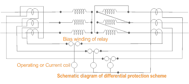
At maximum through fault current, the spill output produced by the small percentage unbalance may be substantial. Therefore, differential protection of transformer should be provided with a proportional bias of an amount which exceeds in effect the maximum ratio deviation.
Circuit Diagram:
Observation Table:
| Sl. No. | Bias Current (IA) (A) | Bias Current (IB) (A) | Relay Operating Current (IC) (A) | Tripping Time (sec) |
| 1. | 0.835 | 5.906 | 5.057 | 0.7 |
| 2. | 0.629 | 5.152 | 4.508 | 0.8 |
| 3. | 1.577 | 5.860 | 4.450 | 0.9 |
| 4. | 1.124 | 4.433 | 3.298 | 1.7 |
| 5. | 1.377 | 4.494 | 3.106 | 2.0 |
| 6. | 1.745 | 4.444 | 2.680 | 3.3 |
| 7. | 1.034 | 3.440 | 2.387 | 4.9 |
| 8. | 2.283 | 4.445 | 2.174 | 20.8 |
| 9. | 5.429 | 2.192 | 3.249 | 21.0 |
Graph:

Apparatus Used:
| Sl. No. | Name of the Apparatus | Specification | Quantity | Maker’s Name |
| 1. | Study of Percentage Bias Transformer Differential Relay Kit | Transformer : 230 / 50-0-50 V | 1 | Diamond Electrotech, Kolkata |
| 2. | Transformer Differential Relay | DDT 12 | 1 | GEC Measurements |
Remarks:
By performing the experiment we have properly tested the operation and behaviour of the percentage biased transformer differential relay.
Related posts:
Views: 358