Experiment No: 6
Experiment Name:
Identify various components of different switchgears: A. Circuit Breaker [: i) LT air circuit breaker; ii) Minimum Oil Circuit Breaker; iii) Air Blast Circuit Breaker; iv) SF6 Circuit Breaker; v) Vacuum Circuit Breaker] B. Isolator [vertical break, horizontal break] C. CTs and PTs D. Power and distribution Transformers and write their specifications.
Objective:
- To identify various components of different switchgears:
A. Circuit Breaker [: i) LT air circuit breaker; ii) Minimum Oil Circuit Breaker; iii) Air Blast Circuit Breaker; iv) SF6 Circuit Breaker; v) Vacuum Circuit Breaker]
B. Isolator [vertical break, horizontal break]
C. CTs and PTs
D. Power and distribution Transformers
2. To write their specifications.
Theory:
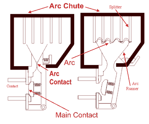
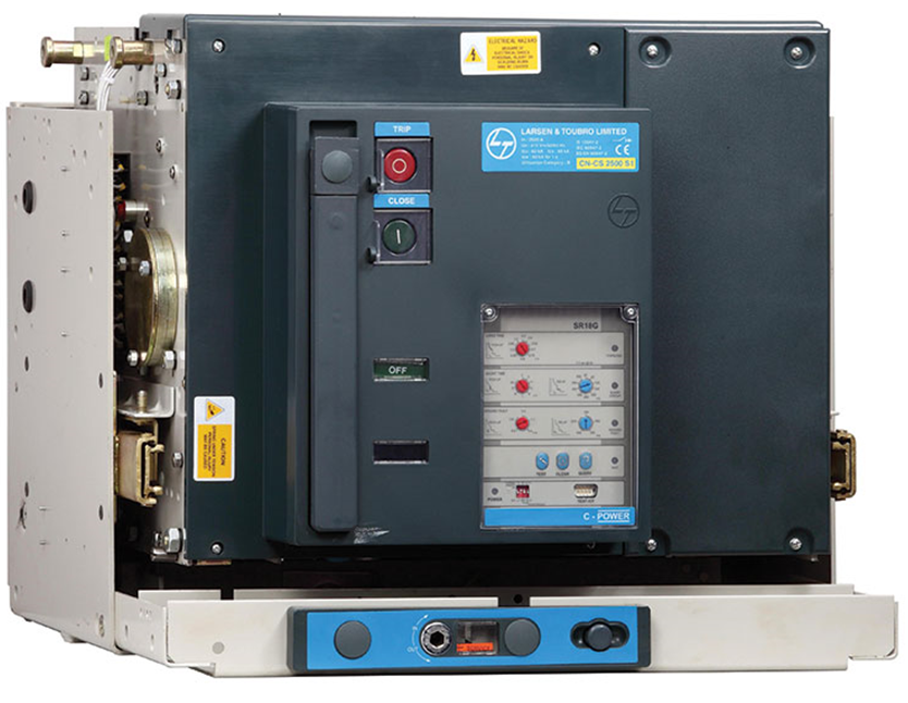
(i) LOW TENSION AIR BREAK CIRCUIT BREAKER: Air Circuit Breaker (ACB) is an electrical device used to provide Overcurrent and short-circuit protection for electric circuits over 800 Amps to 10K Amps. These are usually used in low voltage applications below 450V. We can find these systems in Distribution Panels (below 450V).
Specification:
- Ratings : 400A to 6300A
- Breaking Capacities : 50kA to 100kA
- 3 Pole / 4 Pole Versions with Fix / Draw-out configuration
- High Short time withstand capacity, Icu=Ics=Icw for 1 sec for total selectivity
- Different terminal orientations : Flat, Horizontal and Vertical
Figure:
(ii) MINIMUM OIL CIRCUIT BREAKER:
In a minimum oil circuit breaker very small quantity of insulating oil is used in the arc extinguishing chamber. For insulation purposes, different insulating materials like porcelain, bakelised paper, glass-fiber, etc. are used. The construction of a low oil circuit breaker is shown in the figure. It is made up of two oil-filled chambers, which are known as the upper chamber and lower chamber and are separated from each other. The arc is extinguished in the upper chamber; therefore, it is also known as the arcing chamber.
This arcing chamber consists of an arc control device, an upper fixed contact, and a lower moving contact. The whole assembly of the arc control device, upper contact, lower contact is immersed in oil and enclosed in a glass fiber enclosure. The oil of the lower chamber is used for insulation purposes. It does not get engaged in the arc extinguishing process. Both upper and lower chambers are individually surrounded by cylindrical shaped synthetic resin bonded paper within a porcelain insulator. An operating rod is permanently connected to the moving contact and operating mechanism. It moves vertically to make and break the circuit.
Specification:
These types of circuit breaker are available up to 8000 MVA at 245 KV.
Figure:

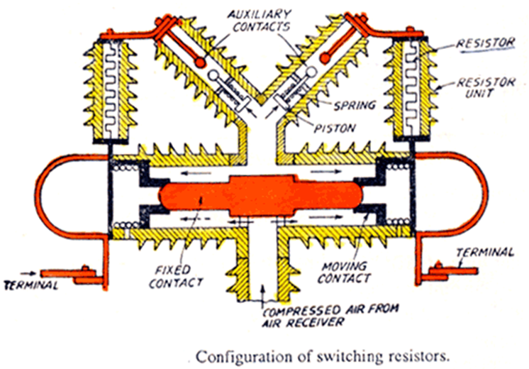
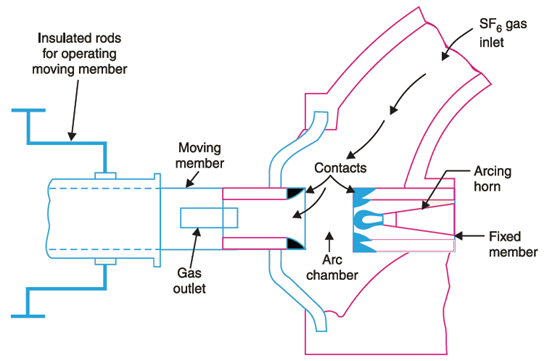
(iii) AIR BLAST CIRCUIT BREAKER: Air blast circuit breaker used compressed air or gas as the arc interrupting medium. In the air blast, circuit breaker compressed air is stored in a tank and released through a nozzle to produce a high-velocity jet; this is used to extinguish the arc. Air blast circuit breakers are used for indoor services in the medium high voltage field and medium rupturing capacity.
Specification: Generally up to voltages of 15 KV and rupturing capacities of 2500 MVA. The air blast circuit breaker is now employed in high voltage circuits in the outdoors switch yard for 220 KV lines. Air blast circuit breakers are classified on the basis the direction of air blast to the arc.
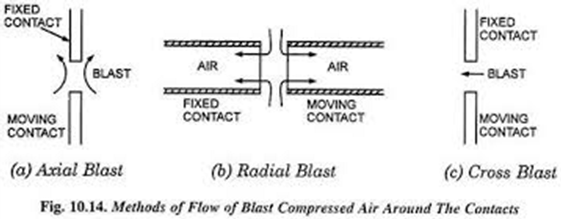
They are classified into :
- Axial Blast Type – air blast is directed along the arc path.
- Cross Blast Type – air blast is directed at right angles to the arc path.
- Radial Blast Type – air blast is directed radially.
Figure:
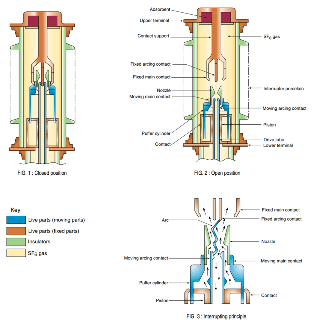
(iv) SF6 CIRCUIT BREAKER: In an SF6 Circuit breaker, sulphur hexafluoride gas is used as the arc quenching medium. The sulphur hexafluoride gas (SF6) is an electronegative gas and has a strong tendency to absorb free electrons. The contacts of the breaker are opened in a high-pressure flow sulphur hexafluoride (SF6) gas and an arc is struck between them. The gas captures the conducting free electrons in the arc to form relatively immobile negative ions. This loss of conducting electrons in the arc quickly builds up enough insulation strength to extinguish the arc. Comparing to other circuit breaker types, the SF6 circuit breakers have been found to be very effective for high power and high voltage service.
In the closed position of the breaker, the contacts remain surrounded by sulphur hexafluoride gas (SF6) gas at a pressure of about 2.8 kg/cm2.
When the breaker operates, the moving contact is pulled apart and an arc is struck between the contacts. The movement of the moving contact is synchronized with the opening of a valve. The valve permits sulphur hexafluoride gas (SF6) gas at 14 kg/cm2 pressure from the reservoir to the arc interruption chamber.The high-pressure flow of sulphur hexafluoride gas (SF6) rapidly absorbs the free electrons in the arc path. It forms immobile negative ions which are ineffective as charge carriers.The result is that the medium between the contacts quickly builds up high dielectric strength and causes the extinction of the arc.
After the breaker operation (i.e. after arc extinction in circuit breaker), the valve is closed by the action of a set of springs.
Specification: SF6 CBs are available for all voltages ranging from 144 to 765 kV or even above. Continuous currents up to 8000 A, and symmetrical interrupting ratings up to 63 kA at 765 kV and 80 kA at 230 kV.
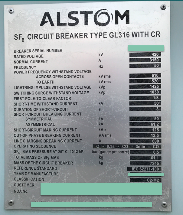
Figure:
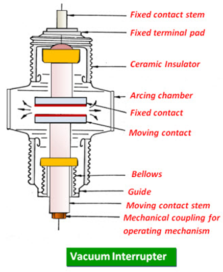
(v) VACUUM CIRCUIT BREAKER: A vacuum circuit breaker is such kind of circuit breaker where the arc quenching takes place in vacuum. The technology is suitable for mainly medium voltage application. For higher voltage vacuum technology has been developed but not commercially viable. The operation of opening and closing of current carrying contacts and associated arc interruption take place in a vacuum chamber in the breaker which is called vacuum interrupter. The vacuum interrupter consists of a steel arc chamber in the centre symmetrically arranged ceramic insulators. The vacuum pressure inside a vacuum interrupter is normally maintained at 10– 6 bar.
The material used for current carrying contacts plays an important role in the performance of the vacuum circuit breaker. Cu/Cr is the ideal material to make VCB contacts. The vacuum circuit breaker is today recognized as most reliable current interruption technology for medium voltage switchgear. It requires minimum maintenance compared to other circuit breaker technologies.
Specification:
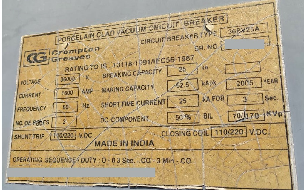
Figure:
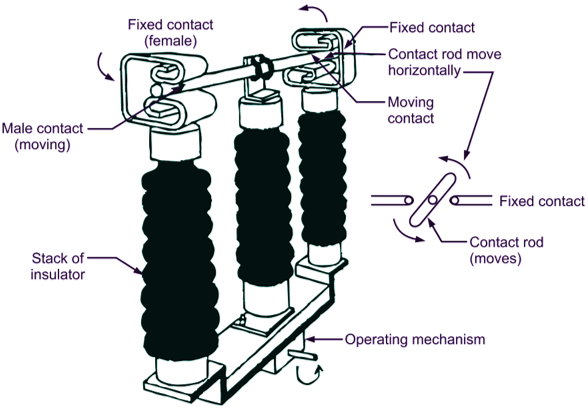
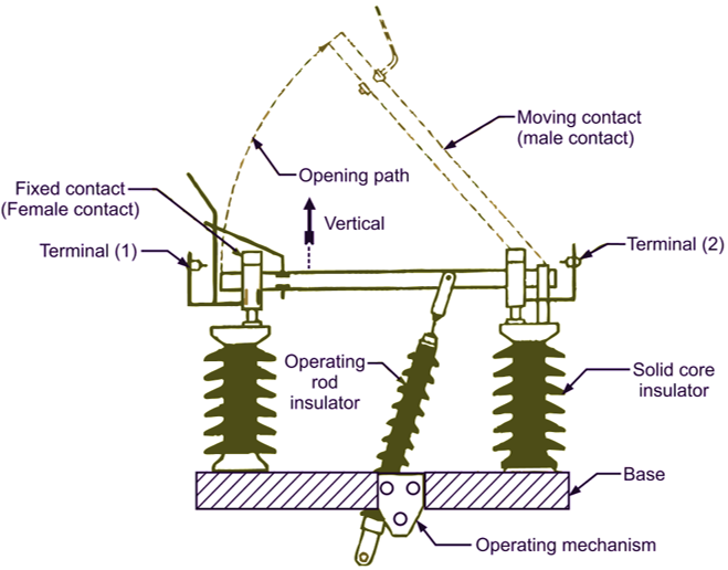
B. ISOLATOR : The isolator can be defined as; it is one type of mechanical switch used to isolate a fraction of the electrical circuit when it is required. Isolator switches are used for opening an electrical circuit in the no-load condition. It is not proposed to be opened while current flows through the line. Generally, these are employed on circuit breaker both the ends thus the circuit breaker repair can be done easily without any risk. Electrical Isolator is used to separate any type of electrical component from the system while the system is offline/ online. Isolator doesn’t include any kind of system for avoiding arching throughout disconnection. As in an electrical substation, an electrical isolator switch is mainly used for disconnecting a power transformer once it is in a no-load situation otherwise a little load is there. In full load condition, isolators don’t operate.
Specification: The Isolators shall be suitable to carry the rated current continuously and full short circuit current of 63/40/31.5/25 KA for 400/220/132/33 KV respectively for 3 second at site condition without any appreciable rise in temperature. These shall also be suitable for operation at 110% rated (normal) voltage.
Figure:
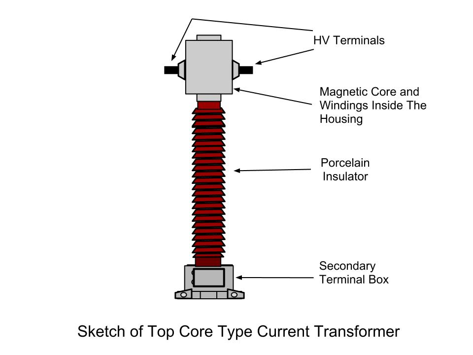
C. CT (CURRENT TRANSFORMER): The Current Transformer, is a type of “instrument transformer” that is designed to produce an alternating current in its secondary winding which is proportional to the current being measured in its primary. Current transformers reduce high voltage currents to a much lower value and provide a convenient way of safely monitoring the actual electrical current flowing in an AC transmission line using a standard ammeter.
Specification:
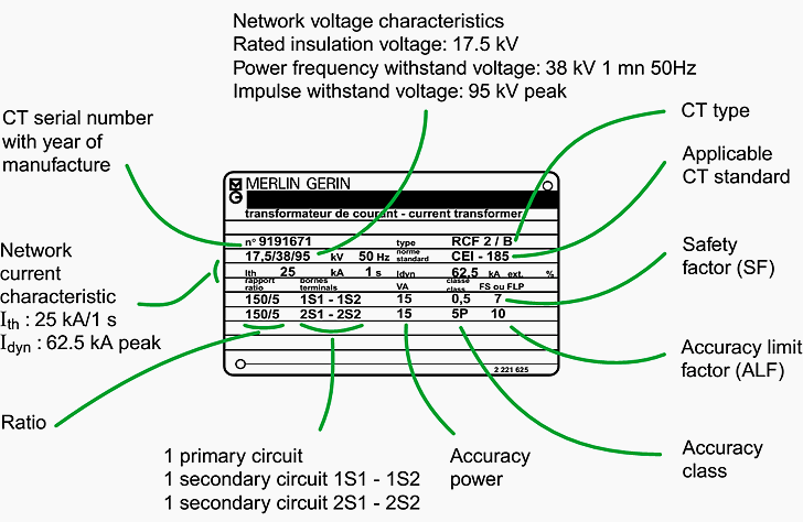
Figure:

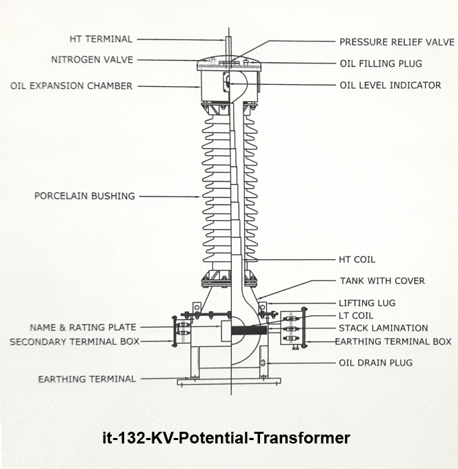
C. PT (POTENTIAL TRANSFORMER): A potential transformer (P.T.) is an instrument transformer which is used for the protection and measurement purposes in the power systems. A potential transformer is mainly used to measure high alternating voltage in a power system. Potential transformers are step-down transformers, i.e., they have many turns in the primary winding while the secondary has few turns. The figure shows a typical potential transformer for the measurement of high alternating voltage. From the figure, it is clear that a P.T. is a well designed step down transformer.
Specification:
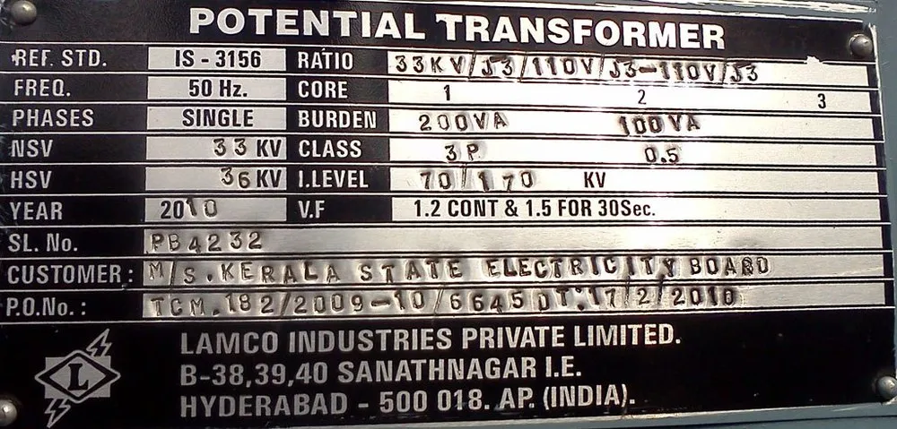
Figure:
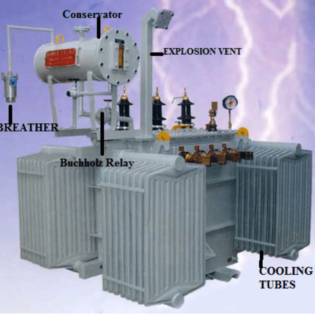
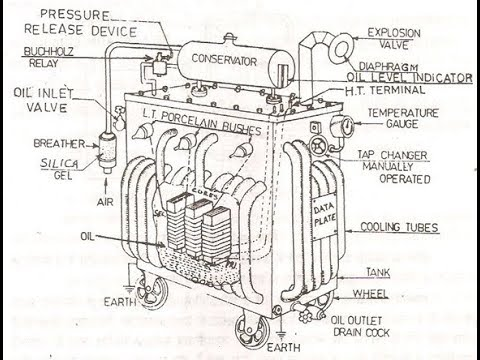
D. POWER TRANSFORMER: A power transformer is a static machine used for transforming power from one circuit to another without changing the frequency. Transformers operate based on the principle of mutual induction. Generation of electrical power in low voltage level is very much cost effective. Theoretically, this low voltage level power can be transmitted to the receiving end. This low voltage power if transmitted results in greater line current which indeed causes more line losses.
Specification:
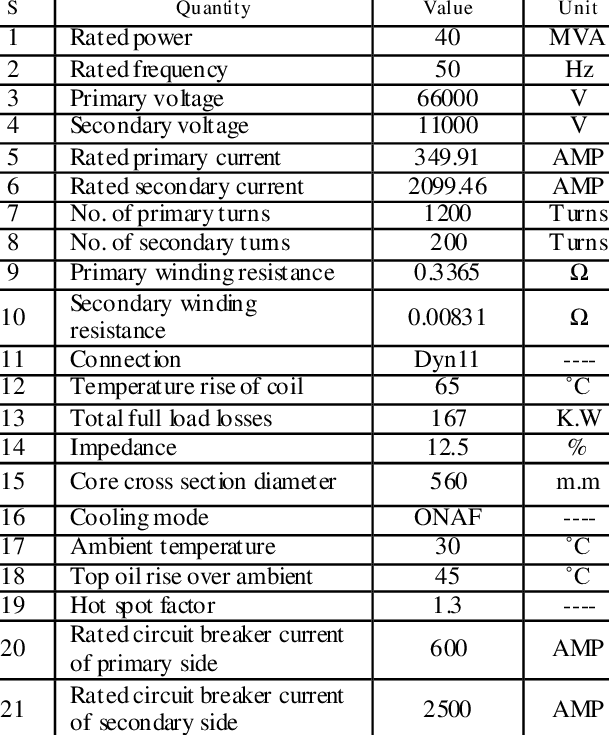
Figure:
D. DISTRIBUTION TRANSFORMER: A distribution transformer is a transformer that provides the final voltage transformation in the electric power distribution system, stepping down the voltage used in the distribution lines to the level used by the customer. It is mainly mounted on a utility pole, they are called pole-mount transformers. If the distribution lines are located at ground level or underground, distribution transformers are mounted on concrete pads and locked in steel cases, thus known as distribution tap pad-mount transformers.
Distribution transformers normally have ratings less than 200 kVA, although some national standards can allow for units up to 5000 kVA to be described as distribution transformers. Since distribution transformers are energized for 24 hours a day (even when they don’t carry any load), reducing iron losses has an important role in their design. As they usually don’t operate at full load, they are designed to have maximum efficiency at lower loads. To have a better efficiency, voltage regulation in these transformers should be kept to a minimum. Hence they are designed to have small leakage reactance.
Specification:
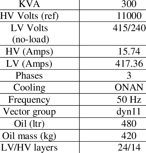
Figure:
Related posts:
Views: 3959