Experiment No.: 2
Experiment Name:
Testing of static Overcurrent protection relay using Relay Testing Kit.
Objective:
To test static overcurrent protection relay using Relay Testing Kit.
Theory:
The overcurrent relays, even though simplest of all types of electromechanical relays, are the most difficult static relays. This is because the induction disc characteristics of the overcurrent relays (inverse characteristics) are not amenable to simple mathematical analysis. The first static relays developed were the high speed differential relays and the distance relays.
Fault current level detectors are termed overcurrent relays. They are more complicated in static form as compared to their electromagnetic counterparts.
Block Diagram of static overcurrent protection relay:
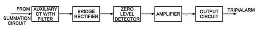
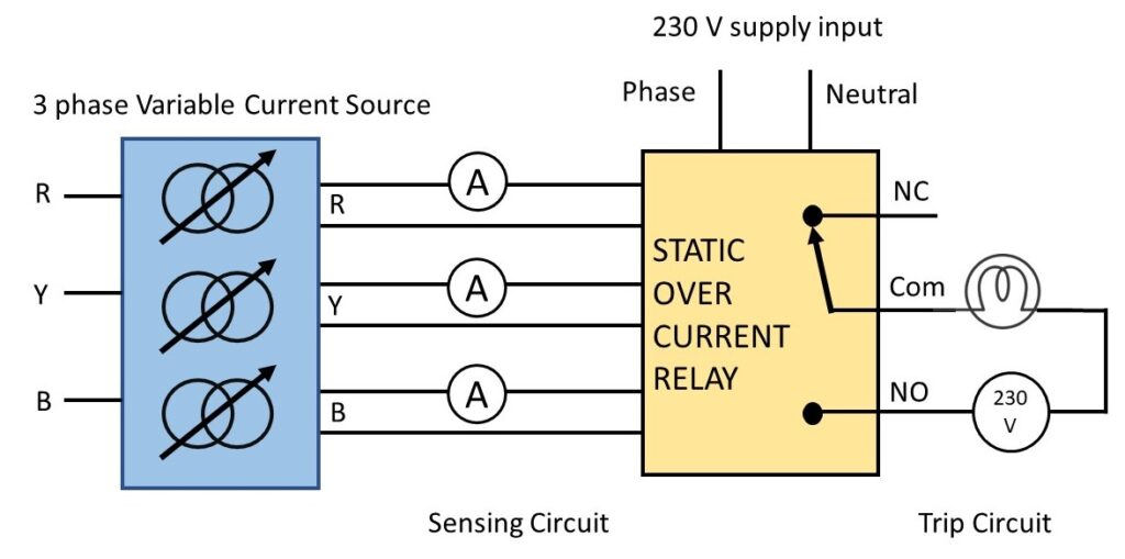
Circuit Diagram for the experiment:
Observation Table:
| Sl. No. | IR (A) | IY (A) | IB (A) | Set Current in Relay (A) | Tripping Time (mS) |
| 1. | 2.0 | 3.66 | 2.02 | 3 | 41 |
| 2. | 3.84 | 2.11 | 2.02 | 3.5 | 44 |
| 3. | 3.28 | 3.21 | 7.74 | 4 | 37 |
| 4. | 3.28 | 3.21 | 9.81 | 4 | 19 |
Procedure:
- Connect the instruments as shown in circuit diagram.
- Set the OC Relay current setting knob and time delay knob in a perticular position, say 3 A and 0.5 sec. That means if any of the phase current exceed the value of 3 A, then the relay will sense this fault and close the trip contacts.
- Increase the variac knob for generating fault in any of the phase.
- The relay close the trip contacts only when the phase current exceed the value of 3 A (in this case)
- Thus after changing the current setting, take different readings. Make a stopwatch ready, it will help to measure the tripping time.
Apparatus Used:
| Sl. No. | Name of the Apparatus | Specifiaction | Quantity | Maker’s Name |
| 1. | Three Phase Over Current Realy | Supply: 240 V AC O/C Trip Time: 0-15 sec O/C set: 0.5-5 A | 1 | PiC |
| 2. | Relay Testing Kit | 415 V, 50 Hz, input | 1 | Tech Track |
| 3. | GLS Bulb for Trip Circuit | 240 V AC, 200 W, Incandescent Bulb | 1 | Philips |
Remarks:
Views: 1139
Very good idea
YES