Experiment No.: 5
Experiment Name: Testing of Induction Type Over Current Relay using Relay Testing Kit to Plot the Inverse Characteristics.
Theory:
A non-directional heavily damped induction disc relay which has an adjustable inverse time/current characteristic with a definite minimum time. The relay has a high torque movement combined with low burden and low overshoot. The relay disc is so shaped that as it rotates the driving torque increases and offsets the changing restraining torque of the control spring. This feature combined with the high torque of the relay ensures good contact pressure even at currents near pick-up. Damping of the disc movement is by a removable high retentively permanent magnet. The unique method of winding the operating coil ensures that the time/current characteristics are identical on each of the seven current taps. Selection of the required current setting is by means of a plug setting bridge which has a single insulated plug. The maximum current tap is automatically connected when the plug is withdrawn from the bridge, allowing the setting to be changed under load without risk of open circuiting the current transformers. The IDMT relay has an auxiliary unit which is powered by a secondary winding on the electromagnet through a rectifier and as such a separate auxiliary supply is not required. The disc unit operates and closes its contacts, the auxiliary element connected across the secondary winding on the electromagnet operates, and one normally open contact of the auxiliary element reinforces the disc contact.
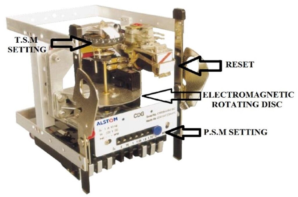
Pick-up Current: In all electrical relays, the moving contacts are not free to move. All the contacts remain in their respective normal position by some force applied on them continuously. This force is called controlling force of the relay. The current for which the relay initiates it operation is called pick up current of relay.
Current Setting of Relay: The minimum pick up value of the deflecting force of an electrical relay is constant. Again the deflecting force of the coil is proportional to its number of turns and current flowing through the coil. Now, if we can change the number of active turns of any coil, the required current to reach at minimum pick value of the deflecting force, in the coil also changes. That means if active turns of the relay coil is reduced, then proportionately more current is required to produce desired relay actuating force. Similarly if active turns of the relay coil are increased, then proportionately reduced current is required to produce same desired deflecting force. Practically same model relays may be used in different systems. As per these systems requirement the pick-up current of relay is adjusted. This is known as current setting of relay. This is achieved by providing required number of tapping in the coil. These taps are brought out to a plug bridge. The number of active turns in the coil can be changed by inserting plug in different points in the bridge The current setting of relay is expressed in percentage ratio of relay pick up current to rated secondary current of CT.
For example, an over current relay should operate when the system current just crosses 125% of rated current. If the relay is rated with 1 A, the normal pick up current of the relay is 1 A and it should be equal to secondary rated current of current transformer connected to the relay. Then, the relay will be operated when the current of CT secondary becomes more than or equal 1.25 A. As per definition, The current setting is sometimes referred as current plug setting. The current setting of over current relay is generally ranged from 50% to 200%, in steps of 25%. For earth fault relay it is from 10% to 70% in steps of 10%. Hence, pick up current of the relay is, 1 × 150 % = 1.5 A. Now, suppose fault current in the CT primary is 1000 A. Hence, fault current in the CT secondary i.e. in the relay coil is, 1000 × 1/200 = 5 A. Therefore PSM of the relay is, 5 / 1.5 =3.33
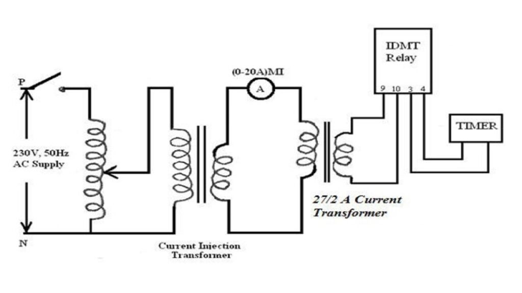
Circuit Diagram:
Observation Table:
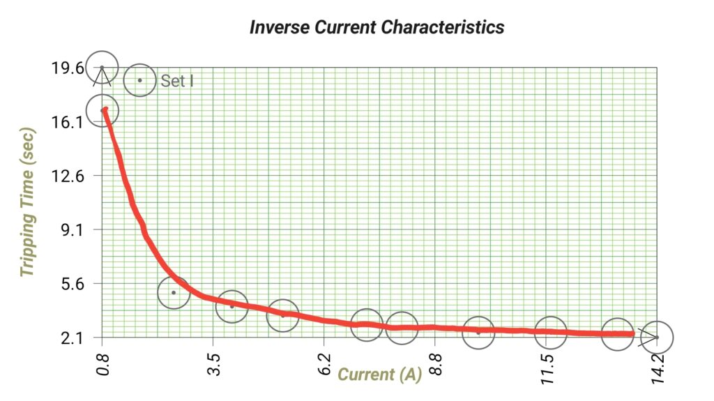
CT Current Setting : 1A
| Sl. No. | Current (A) | Tripping Time |
| 1. | 0.80 | 19.6 |
| 2. | 0.81 | 16.8 |
| 3. | 2.53 | 5.0 |
| 4. | 3.94 | 4.1 |
| 5. | 5.17 | 3.5 |
| 6. | 7.19 | 2.9 |
| 7. | 8.04 | 2.7 |
| 8. | 9.89 | 2.4 |
| 9. | 11.64 | 2.4 |
| 10. | 13.25 | 2.3 |
| 11. | 14.20 | 2.1 |
Graph:
Apparatus Used:
| Sl. No. | Name of the Apparatus | Specification | Quantity | Maker’s Name |
| 1. | Over Current Relay | Inverse Type, CDG (Current operated, Disk type, General purpose), CT Current Setting: 0.5-2A | 1 | ALSTOM |
| 2. | Over Current Relay Testing Kit | 230 V, 50Hz Input | 1 | M.E.W. |
| 3. | Clip-on Ammeter | 0-1000A | 1 | Metravi |
Remarks: The alarm was not ringing after tripping the relay. The timer of the overcurrent relay testing kit was not stopping automatically after tripping the relay, so, we had to stop it manually. As a result the the observed time is not so accurate. Except this the inversce current characteristics is observed successfully.
Views: 1513