Experiment No.: 2
Experiment Name:
Speed Measurement by using Stroboscope
Objective:
To measure speed by usinh Stroboscope
Theory:
The primary use for a stroboscope is to stop motion for diagnostic inspection purposes. However, the stroboscope can be used to measure speed. In order to do this, several factors need to be considered. First, the object being measured should be visible for all 360° of rotation (e.g. The end of a shaft). Second, the object should have some unique part on it, like a bolt, keyway or imperfection to use as a reference point.

If the object being viewed is perfectly symmetrical, then the user needs to mark the object with a piece of tape or paint in a single location only, to be used as a reference point. If the speed of rotation is within the range of the stroboscope, start at the highest flash rate and adjust the flash rate down. At some point motion to be stopped with only a single image of the object in view. Noted that at a flash rate twice the actual speed of the image two images will be seen. After approaching the correct speed, can be seen three, four or more images at harmonics of the actual speed. The first SINGLE image seen is the true speed. To confirm the true speed, noted the reading and adjust the stroboscope to exactly half this reading, or just press the ÷2 button. Then again seen a single image (which may be phase shifted with respect to the first image seen).
For example, when viewing a shaft with a single keyway, you will see one stationary image of the keyway at the actual speed and at 1/2, 1/3, ¼, etc. of the actual speed. You will see 2 images of the key way at 2 times the actual speed, 3 key way at 3 times, etc. The FPM (Flash per minuet) equals the shafts revolutions per minute (RPM) at the highest flash rate that gives only one stationary image of the keyway.

Stroboscopes must be used when you can’t shut down the device. The human eye is not easily tricked into seeing a stopped image by a stroboscope when the flash rate is slower than 300 FPM. Therefore, stroboscopes are just about impossible to use below 300 FPM for inspection or to measure RPM.
Block Diagram of Stroboscope:

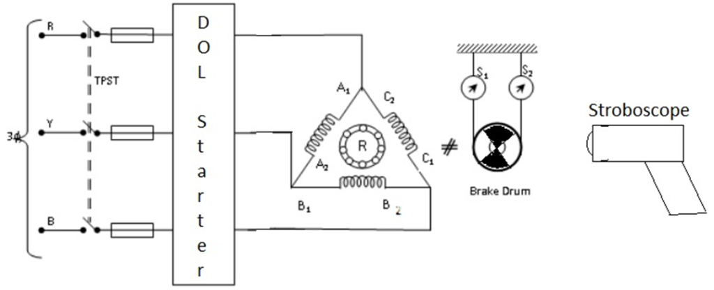
Experimental Setup:

Procedure:
- Connect the 3 phase induction motor as shown in figure.
- Release the brake drum for no load speed measurement.
- Run the motor and note the speed shown by stroboscope.
Observation Table:
| Sl. No. | Applied load (kg) | Speed (RPM) |
Apparatus Used:
| Sl No. | Name of Apparatus | Quantity | Specification | Makers name |
| 1. | ||||
| 2. | ||||
| 3. |
Remarks:
Views: 13

Nice explanation
Thank you!