Experiment No.: 3
Experiment Name:
Calibration of given LVDT
Objective:
- To measure Linear displacement by LVDT
- To plot displacement v/s output voltage characteristics curve
Theory:
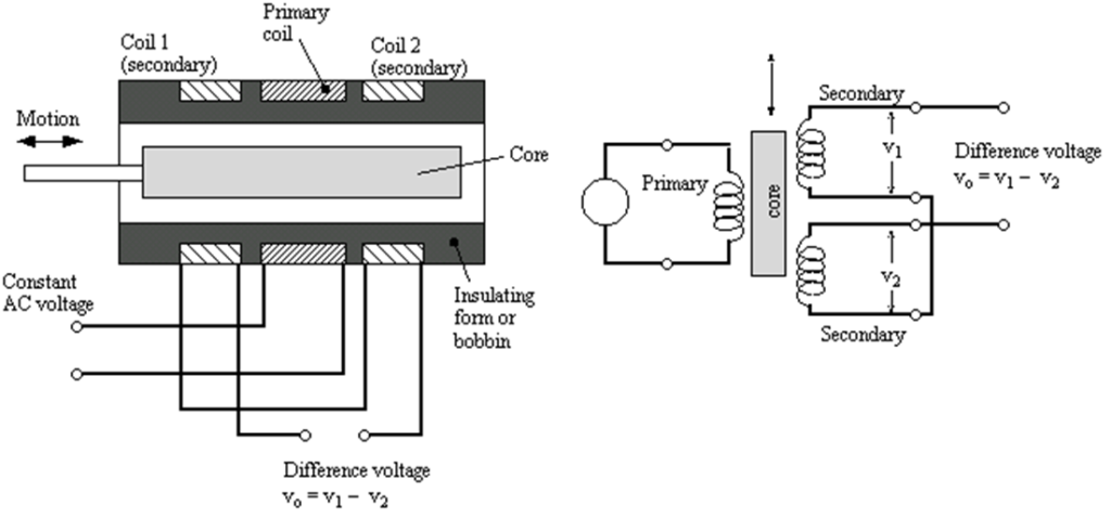
The most widely used inductive transducer to translate the linear motion into electrical signal is the Linear Variable Differential Transducer (LVDT).
The basic construction of LVDT is given in the figure. The transformer consists of a single primary winding P1 and two secondary winding S1and S2 wound on a cylindrical former. The secondary winding has equal number of turns and is identically placed on either side of the primary winding. The primary winding is connected to an alternating current source. A movable soft iron core is placed inside the former. The displacement to be measured to be applied to an arm attached to the soft iron core. When the core is in its normal (null) position equal voltage are induced in two secondary windings. The frequency of a.c. applied to primary winding may be between 50 Hz to 20 kHz.
Circuit Diagram:
Observation Table:
| Sl. No. | Displacement (mm) | Output voltage (mV) | Sl. No. | Displacement (mm) | Output voltage (mV) |
Graph:
Plot displacement v/s output voltage characteristics curve.
Remarks:
Views: 28