Experiment No.: 5
Experiment Name:
Determination of negative temperature coefficient and calibration of a Thermister
Objective:
To determine negetive temperature coefficient and calibrate a Thermistor
Theory:
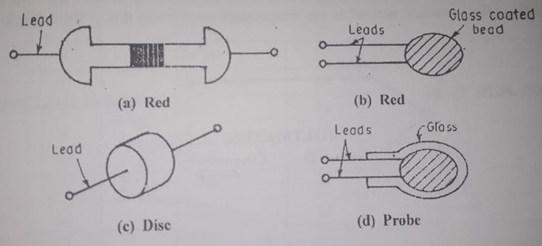
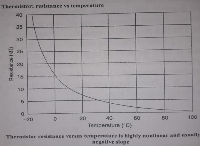
Thermistor (10 K): Thermistor is a contraction of a term thermal resistor. Although positive temperature co-efficient (P.T.C) of unit exhibit an increase in the value of resistance with increase in temperature are available, most Thermistor have a negative temperature coefficient i.e. their resistance decreases with increase in temperature. In some materials the resistance of Thermistor at room temperature may decrease as much as 6% for 1°C rise in temperature. This high sensitivity to temperature change make the Thermistor extremely well suited to precision temperature measurement, control & compensation. Therefore, especially in lower temperatures range of -100°C to 300°C, or to detect very small changes in temperature which cannot be observed with an RTD or a thermocouple. Thermistor is composed of a sintered mixture of metallic oxides, such as Mn, Ni, Co, Cu, Fe, & U. Their resistance range from 0.5 Ω to 75 MΩ and they are available in wide variety of shapes and sizes.
· Semiconductor resistance sensors
· Unlike metals, Thermistor respond negatively to temperature and their coefficient of resistance is of the order of 10 times higher than that of platinum or copper.
If temperature increases, then semiconductor resistance decreases
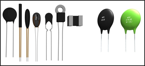
Smallest in size are the beads with a diameter of 0 .15 mm to 1.25 mm.
In conventional temperature measurement application, the Thermistor forms of one of the arms of the wheat-stone bridge. Any change in the Thermistor resistance as a result of temperature change is reflected in the readout device.
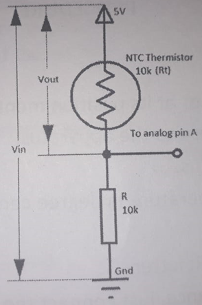
Circuit Diagram:
Procedure:
- Connect the 10K Thermistor sensor at its position mentioned on front panel.
- Connect the power cord to the apparatus.
- Switch on the apparatus.
- User can see the temperature in degree centigrade on second position of 16×2 display.
- Observe the voltage change due to temperature on test point provided on front panel (Blue socket w.r.t Ground).
Observation Table:
| Time (min.) | 0 | 1 | 2 | 3 | 4 | 5 | 6 | 7 | 8 | 9 | 10 | |
| Temperature (K) | ||||||||||||
| Temperature (OC) | ||||||||||||
| Vout from Thermister | ||||||||||||
| Thermister Resistance (R1) (Ω) |
Graph:
Remarks:
Views: 17
Good post. I learn something totally new and challenging on websites I stumbleupon everyday. It will always be useful to read through articles from other writers and practice a little something from other sites.