Experiment No.: 4
Experiment Name:
Test the performance of given UPS
Objective:
To test the performance of given UPS
Theory:
An uninterruptible power supply or uninterruptible power source (UPS) is an electrical apparatus that provides emergency power to a load when the input power source or mains power fails. A UPS differs from an auxiliary or emergency power system or standby generator in that it will provide near-instantaneous protection from input power interruptions, by supplying energy stored in batteries, super capacitors, or flywheels. The on-battery run-time of most uninterruptible power sources is relatively short (only a few minutes) but sufficient to start a standby power source or properly shut down the protected equipment. It is a type of continual power system.
The UPS trainer kit demonstrates the principle of a PWM inverter that is a DC to AC converter and uses a custom programmed microcontroller. MOSFETs are used as switching devices. When AC power is available, the UPS automatically transfer the AC power to load. The input of AC power is indicated by the yellow LED near AC input terminal.
The transfer to AC is indicated by the AC relay LED. After AC power is stable, another tap is selected in the transformer indicated by another red LED and changing begins.
Note that the charger OFF LED is turned off at that time. When charging complete the charger OFF LED start glowing, indicating that the charger has been turned off.
In the absence of input AC power, if the UPS mode is ON (Indicated by Green UPS LED) the UPS automatically starts the inverter, which is indicated by the INV ON (inverter ON LED).
The charger runs from the 18 V AC winding of the transformer. During inverter mode the charger is turned off. This is indicated by the charger OFF LED (Green).
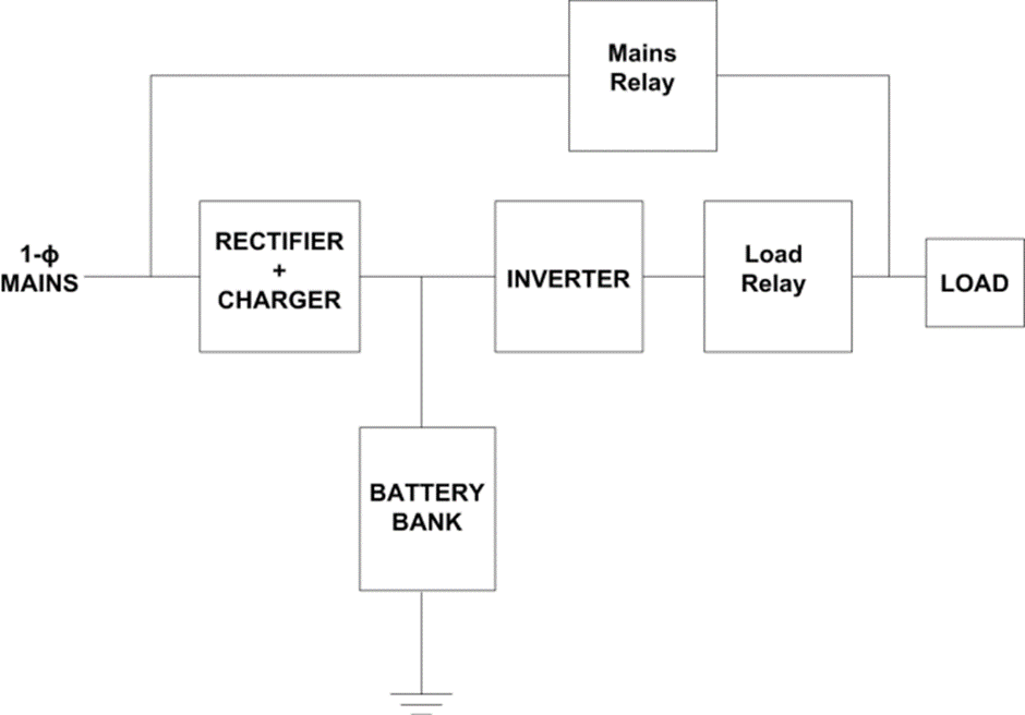
Block Diagram:
Experimental Procedure:
- Connect battery
- Connect lamp load
- Connect AC power
- AC relay should turn ON and lamp should glow
- Now turn OFF the AC power
- Lamp should turn OFF
- Press the RUN button (UPS LED should glow)
- The lamp should turn ON now
- The INV-ON (Inverter ON LED should glow).
- Adjust the PWM and hence the relevant voltage using the + and – button
- The PWM waveform can be checked in the test points. It is a push pull inverter working at a frequency of 50 Hz. So the maximum time period for each cycle is 10 ms. However due to PWM (Pulse Width Modulation the duty cycle of the period is decrease to decrease the output voltage)
- Now reapply AC power check transfer from inverter mode on battery to mains AC.
Apparatus used:
| Sl No. | Name of Apparatus | Specification | Quantity | Makers name |
| 1. | UPS trainer Kit | 230 V AC / 12 V DC | 1 | Microline |
| 2. | Battery | 12 V, 7 Ah, Lead Acid | 1 |
Remarks: The performance of the UPS is tested successfully.
Views: 2086