Experiment No.: 8
Experiment Name:
Observe the output waveform of half wave-controlled rectifier with resistive load using CRO and determine the load voltage.
Objective:
- To observe the output waveform of half wave-controlled rectifier with resistive load using CRO.
- Determine the load voltage.
Theory:
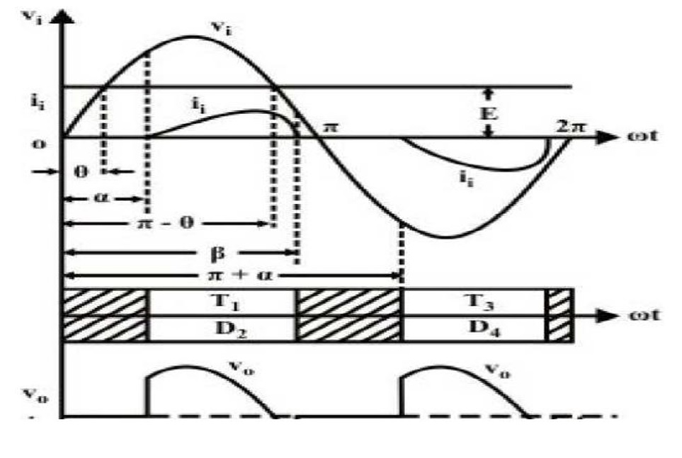
A semi converter uses two diodes and two thyristor and there is a limited control over the level of dc output voltage. A semi converter is one quadrant converter. A one-quadrant converter has same polarity of dc output voltage and current at its output terminals and it is always positive. It is also known as two-pulse converter. Figure shows half controlled rectifier with R load. This circuit consists of two SCRs T1 and T2, two diodes D1 and D2. During the positive half cycle of the ac supply, SCR T1 and diode D2 are forward biased when the SCR T1 is triggered at a firing angle ωt = α, the SCR T1 and diode D2 comes to the on state. Now the load current flows through the path L – T1- R load –D2 – N. During this period, we output voltage and current are positive. At ωt = π, the load voltage and load current reaches to zero, then SCR T1 and diode D2 comes to off state since supply voltage has been reversed. During the negative half cycle of the ac supply, SCR T2 and diode D1 are forward biased. When SCR T2 is triggered at a firing angle ωt = π + α, the SCR T2 and diode D1 comes to on state. Now the load current flows through the path N – T2- R load – D1 -L. During this period, output voltage and output current will be positive. At ωt = 2π, the load voltage and load current reaches to zero then SCR T2 and diode D1 comes to off state since the voltage has been reversed. During the period (π + α to 2π) SCR T2 and diode D1 are conducting. Vout=(√2Vs)(1+cosα)/π.
Circuit Diagram:

Procedure:
- Make the connections as per the circuit diagram.
- Connect CRO and voltmeter across the load.
- Keep the potentiometer at the minimum position.
- Switch on the step down ac source.
- Check the gate pulses at G1-K1 & G2-K2, respectively.
- Observe the wave form on CRO and note the triggering angle ‘α’ and
- Note the corresponding reading of the voltmeter. Also note the value of Maximum amplitude Vm from the waveform.
- Set the potentiometer at different positions and follow the step given in (6) for every position.
- Tabulate the readings in the observation column.
Waveform:
Observation Table:
| Sl. No. | Triggering Angle (α°) | Measured Output Voltage, VO (V) | Time Period (ms) |
| 1. | |||
| 2. | |||
| 3. |
Remarks:
Thus the operation of single phase half controlled converter using resistive load has studied and the output waveforms has been observed.
Related posts:
Views: 609