Experiment No.: 3
Experiment Name:
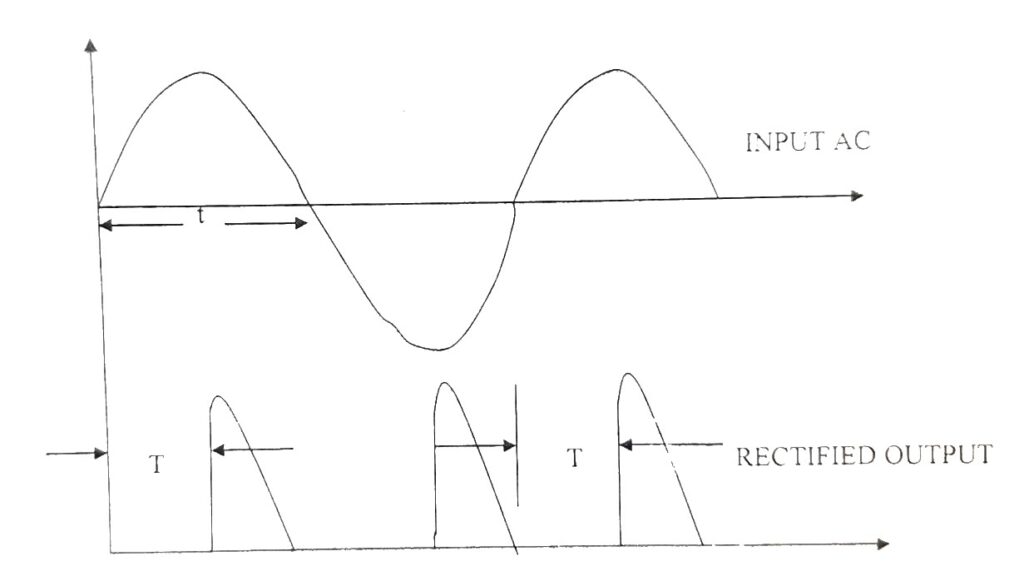
Observation of the Output Waveform of Full Wave-Controlled Rectifier with Resistive Load and Determine the Load Voltage
Objective:
- To observe the output waveform of Full Wave-Controlled Rectifier using four thyrister with Resistive load
- To determine the load voltage
Theory:
Control rectifier used to drive a dc operated system whose power to be controlled. The firing angle of the thyrister is controlled by suitable pulse to its gate terminal. As the firing angle changes, its output gives changed dc voltage. So we can call it as a variable power supply or controllable power supply. So we can call it as a Full Wave Controllable Rectified power supply in Circuit Board Design.
Circuit Diagram:

Procedure:
- The circuit is connected as per the circuit diagram.
- The different test point wave forms are measured.
- Load voltage is measured.
- These waveforms are drawn.
Observed Waveforms:
Observation Table:
| Input AC Voltage | DC Output voltage across the resistive load |
| 12.09 V | 9.35 V |
Apparatus Used:
| Sl. No. | Name of the Apparatus | Specification | Quantity | Maker’s Name |
| 1. | Full Control Converter Trainer kit | 230 V input SCR : TN12 | 1 | ELECTRO-SYS |
| 2. | CRO | Dual Channel, 200 MHz | 1 | Metravi |
| 3. | Digital Multimeter as voltmeter | 0-750 V AC, 0-1000 V DC, 0-10 A | 1 | Akademika |
Remarks:
Output waveforms are observed on the CRO and the voltage across the load is measured successfully.
Views: 894