Experiment No.: 6
Experiment Name:
Demonstration of the improvement of power factor using static condenser.
Objective:
To demonstrate the improvement of p.f. using static condenser.
Theory:
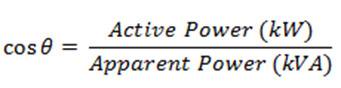
Power factor is a very common term in electrical applications because it determines the efficiency of an electrical system. It is a word that dealing with AC circuits as shown by its simple formula:
It is quite important that the power factor remains close to unity because it indicates higher efficiency of the system. The following devices and equipment are used for Power Factor Improvement.
- Static Capacitor or Static Condenser
- Synchronous Condenser
- Phase Advancer
Here we will discuss about the improvement of Power Factor by using Static Condenser.
Power Factor Improvement by using Static Condenser:
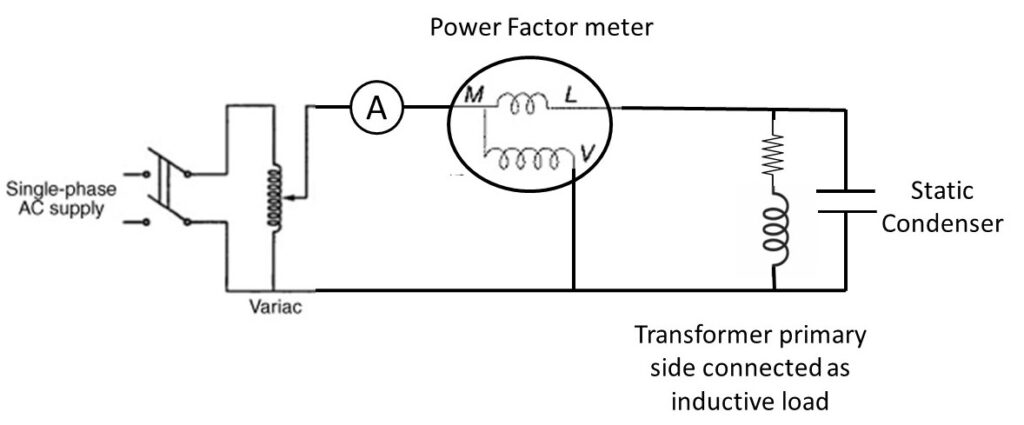
We know that most of the industries and power system loads are inductive that take lagging current which decrease the system power factor. For Power factor improvement purpose, Static capacitors are connected in parallel with those devices which work on low power factor.
These static capacitors provides leading current which neutralize (totally or approximately) the lagging inductive component of load current (i.e. leading component neutralize or eliminate the lagging component of load current) thus power factor of the load circuit is improved. These capacitors are installed in Vicinity of large inductive load e.g Induction motors and transformers etc, and improve the load circuit power factor to improve the system or devises efficiency.
Suppose, here is a single phase inductive load which is taking lagging current (I) and the load power factor is cosΦ1 as shown in fig-1.
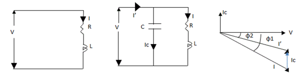
In fig-2, a Capacitor (C) has been connected in parallel with load. Now a current (IC) is flowing through Capacitor which lead 90° from the supply voltage ( Note that Capacitor provides leading Current i.e., In a pure capacitive circuit, Current leading 90° from the supply Voltage, in other words, Voltage are 90° lagging from Current). The load current is (I). The Vectors combination of (I) and (IC) is (I’) which is lagging from voltage at Φ2 as shown in fig 3.It can be seen from fig 3 that angle of Φ2 < Φ1 i.e. angle of Φ2 is less than from angle of Φ1. Therefore cosΦ1 is less than from cosΦ2 (cosΦ2 > cosΦ1). Hence the load power factor is improved by capacitor.
Also noted that after the power factor improvement, the circuit current would be less than from the low power factor circuit current. Also, before and after the power factor improvement, the active component of current would be same in that circuit because capacitor eliminates only the re-active component of current. Also, the Active power (in Watts) would be same after and before power factor improvement.
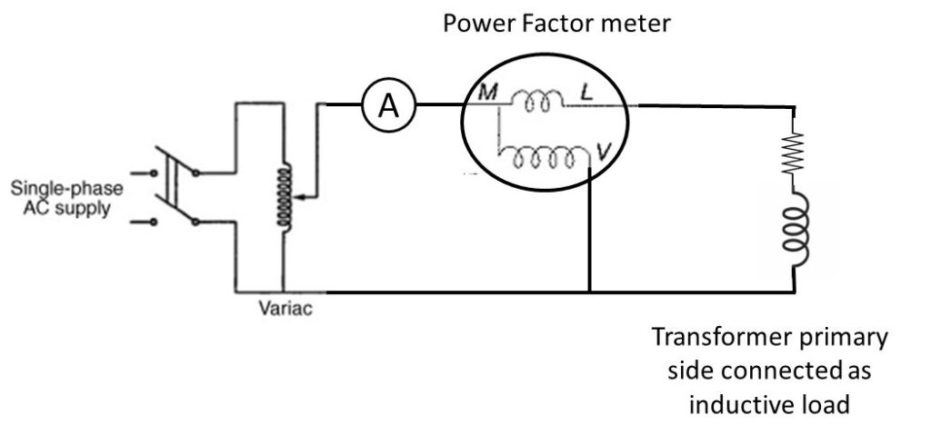
Circuit Diagram:
Observation Table:
| Sl. No. | Load Used | Capacitor Connected | Power Factor | Current (A) | Remarks |
| 1. | Transformer Primary Coil | No Capacitor connected | 0.4 lag | 0.5 A | |
| 2. | Transformer Primary Coil | 2.0 μF | 0.55 lag | 0.44 A | Economical |
| 3. | Transformer Primary Coil | 60 μF | 0.4 lead | 4.01 A |
Apparatus Used:
| Sl. No. | Name of the Apparatus | Specification | Quantity | Maker’s Name |
| 1. | Single phase Variac | 230/0-270 V AC | 1 | |
| 2. | 1-Φ Transformer as inductive load | 230/115 V | 1 | |
| 3. | 1-Φ power factor meter | 0.5 lag – 1 – 0.5 lead | 1 | MECO-G |
| 4. | Capacitor | 2.0 μF ± 5%, 440 V AC, 50 Hz | 1 | USHA |
| 5. | Capacitor | 60.0 μF ± 5%, 440 V AC, 50 Hz | 1 | SYSCAP |
| 6. | Clip-on Ammeter | 0-1000 A AC | 1 | Metravi |
Remarks:
When no capacitor is connected across the load, then the power factor was very low and the current drawn by the load is high. When we connect a capacitor of low value then, the power factor is improved a little bit and the drawn current is reduced a little bit. But when we connect a high value capacitor i.e. 30 times of the previous one, then the power factor changes to very low toward leading and the drawn current becomes very high.
Views: 763