Experiment No.: 3
Experiment Name:
Study of Fully Controlled Full Wave Rectifier using SCR
Objective:
To study Fully Controlled Full Wave Rectifier using SCR
Theory:
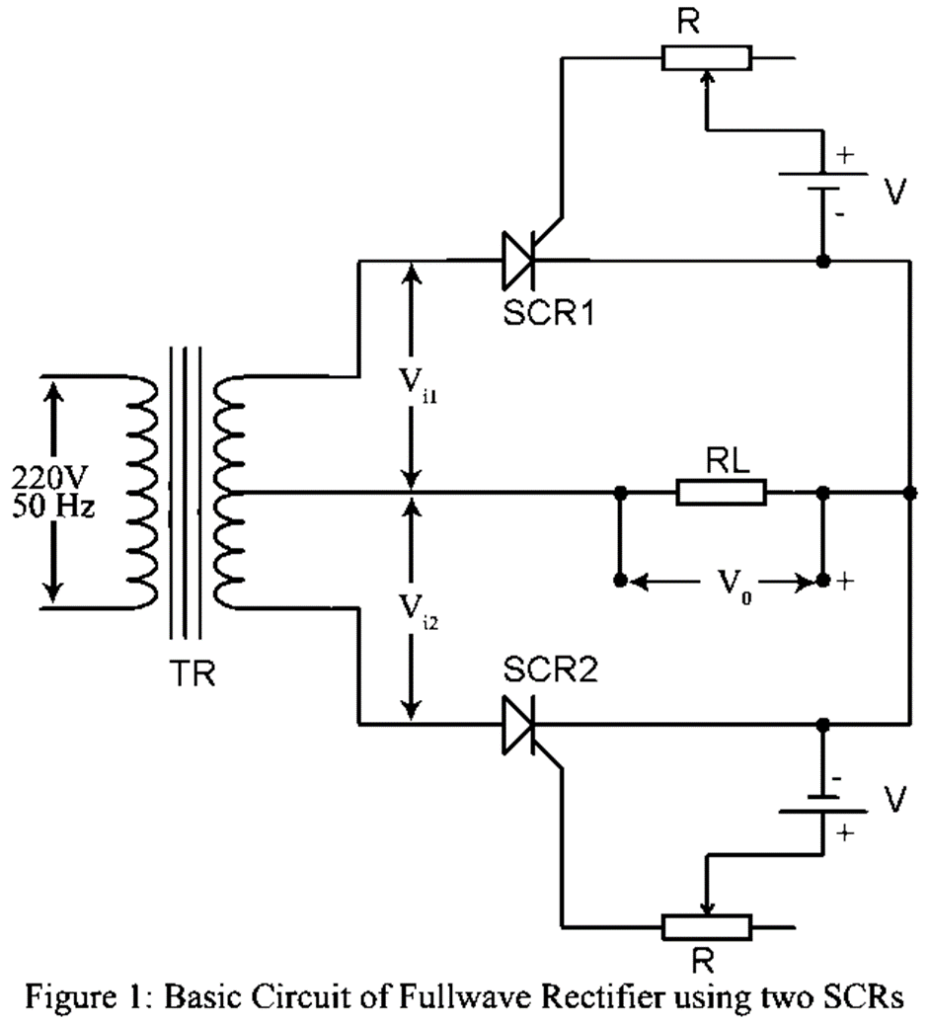
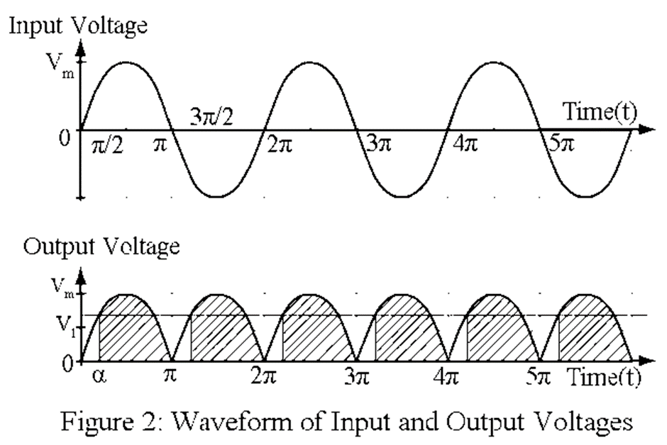
The ac input voltage is fed to the input of a power transformer TR which has centre-tapped secondary. Thus, the voltage Vi1 and Vi2 developed across the two halves of the secondary are equal in magnitude but opposite in phase. These are fed to two identical SCRs with identical gate control circuit. the current of each SCR flows through the load resistor RL in the same direction. Hence one SCR conduct during the positive half cycles of the ac input voltage while the other conducts during the negative halves. Hence, the fullwave output voltage is obtained across RL. Figure 2 shows the output voltage waveform. Here also a filter may be placed between the rectifier and the load resistor RL to remove the ripple voltages.
Circuit Diagram:
Working of Single Phase Full Wave Controlled Rectifier using SCR:
During the positive half cycle of voltage Vi1, SCR1 conducts during the period α to π radians where α is the firing angle. The negative half of Vi1, corresponds to the positive half of Vi2. During this positive half of Vi2, SCR2 conducts during the interval α and π radians. The two outputs get added. The resultant output voltage V0 has the shape shown in figure 2. The output is obtained during the shaded portion. The firing angle α may be changed by changing the gate current by varying the resistor R in the gate control circuit.
Magnitude of Output Volatge and Current:
Let the input voltage Vi1 be a sinusoidal voltage of amplitude Vm and frequency f Hz and let it be given by,
 ………..(1)
Where ω is the angular frequency in radians/second and equals 2πf.
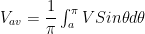
Let, α be the firing angle during the positive half cycle. Then SCR1 conducts during angle α to π radians during the positive half cycle. Hence the average output voltage Vav1 contributed by SCR1 is given by,
 ………(2)
Similarly, the average voltage contributed by SCR2 due to input voltage Vi2 is equal to Vav1. Hence, the total value of average output voltage Vav is given by,
 ……..(3)
![= \dfrac{V_m}{\pi}[-Cos\theta]_{\alpha}^{pi}](https://s0.wp.com/latex.php?latex=+%3D+%5Cdfrac%7BV_m%7D%7B%5Cpi%7D%5B-Cos%5Ctheta%5D_%7B%5Calpha%7D%5E%7Bpi%7D&bg=ffffff&fg=000&s=0&c=20201002)
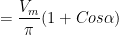 …….(4)
Average output current is,
 ………(5)
We thus, find that fullwave SCR rectifier produces average output voltage and average output current twice those in half wave SCR rectifier. Further, removal of ripple voltage by filter circuit is more effective in full wave SCR rectifier.
Views: 267
It’s hard to come by well-informed people about this subject, however, you sound like you know what you’re talking about! Thanks