Experiment No.: 4(B)
Experiment Name:
Realization of Half Subtractor, Full Subtractor
Objective: To implement the circuit and verify the circuit with truth table of
- Half subtractor
- Full subtractor
Theory:
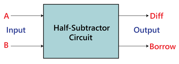
Half subtractor: The half subtractor is also a building block for subtracting two binary numbers. It has two inputs and two outputs. This circuit is used to subtract two single bit binary numbers A and B. The ‘difference’ (D) and ‘borrow’ (B) are two output states of the half subtractor.
Block Diagram:
Truth Table of half subtractor:
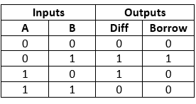
The SOP form of the Diff and Borrow is as follows:
Diff= A’B+AB’
Borrow = A’B
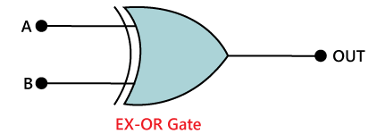
Circuit Diagram of Half Subtractor using Logic Gates:
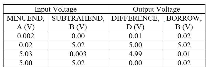
Observation Table:
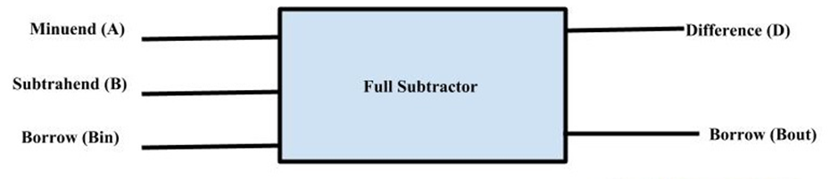
Full Subtractor: A full subtractor is a combinational circuit that performs the arithmetic subtraction of three binary digit. It has 3 input and 2 output i.e. Difference (D) and Borrow (B).
Block Diagram:
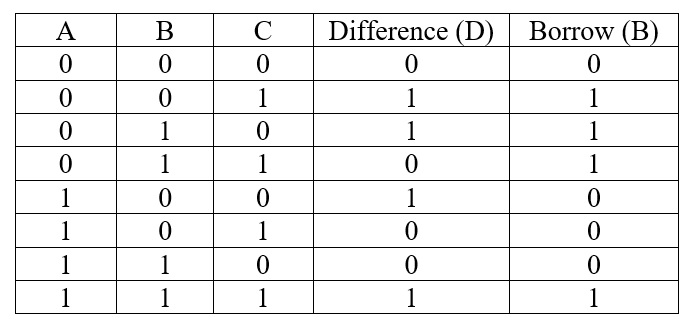
Truth table of Full Subtractor:
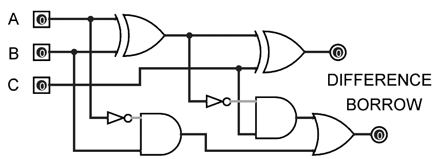
Circuit Diagram of Full Subtractor using Logic Gates:
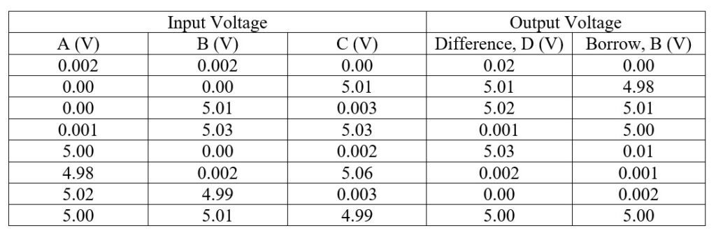
Observation Table:
Apparatus Used:
| Sl No. | Name of Apparatus | Quantity | Specification | Makers name |
| 1. | Logic Gate Trainer Kit | 1 | IC 7432, IC 7408, IC 7404, IC 7400, IC 7402, IC 7404 | Salicon |
| 2. | Connecting Probes | As required | ||
| 3. | Digital Multimeter | 1 | 0-1000 V DC, 0-750 V AC, 0-10 A | Akademika |
Remarks: The half adder and full subtractor circuits are implemented and verified the truth table.
Views: 348