Experiment No.: 6(A)
Experiment Name:
Implementation of Digital to Analog converter using trainer kit.
Objective:
To design and study the digital to analog converter.
Theory:
A digital-to-analog converter (DAC or D-to-A) is a device that converts a digital (usually binary) code to an analog signal (current, voltage, or electric charge). A typical DAC converts the abstract numbers into a concrete sequence of impulses that are then processed by a reconstruction filter using some form of interpolation to fill in data between the impulses.
There are two types D/A converter
- Weighted resistor D/A converter
- D/A converter with ladder N/W.
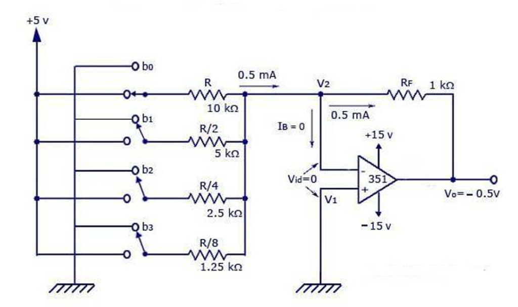
- WEIGHTED D/A CONVERTER:- The binary weighted resistor DAC uses an op- amp to sum n binary weighted currents from a reference voltage VR via current scaling resistor 2R, 4R, 8R, ……2nR. A weighted resistor DAC requires a wide range of resistor values for better resolution whereas a R-2R ladder type DAC requires only two values of resistor .
- D/A CONVERTER WITH LADDER N/W:- In this type reference voltage is applied to one of the switch position , and other switch position is connected to ground .The number of bits can be expanded by adding more sections of same R/2R values.
Circuit Diagram:
Procedure: Functional verification of a weighted resistor D/A converter.
- Make the connection as shown in circuit diagram.
- Connect the power supply to the board.
- Connect the logic switches to the corresponding jacks B0 – B3 of the converter.
- Set the switches S0 – S3 to logic level 0.
- Connect the Vref socket to +5 volts.
- Connect a multimeter as voltmeter for DC, to the output Vo of the converter.
- Switch the logic switches in binary progression & measure & record the output voltage in correspondence of every Combination of the input code.
Observation Table:
| Sl. No. | S3 | S2 | S1 | S0 | VO (Volt) |
| 1. | 0 | 0 | 0 | 0 | 0.02 |
| 2. | 0 | 0 | 0 | 1 | 1.2 |
| 3. | 0 | 0 | 1 | 0 | 1.98 |
| 4. | 0 | 0 | 1 | 1 | 3.36 |
| 5. | 0 | 1 | 0 | 0 | 4.87 |
| 6. | 0 | 1 | 0 | 1 | 5.03 |
Apparatus Used:
| Sl. No. | Name of the Apparatus | Specification | Quantity | Maker’s Name |
| 1. | DAC Trainer Kit | 230 V input | 1 | Excel |
| 2. | Patch Cord | As required | ||
| 3. | Digital Multimeter | 0-750 V AC, 0-1000 V DC, 0-10 A | 1 | Akademika |
Result:
The DA converter is studied & observations are recorded in observation tables.
Precaution:
All the connections should be right and made according to connection diagram. Switched on the power supply after checking the connections. Reading should be taken carefully consciously.
Views: 221
You need to be a part of a contest for one of the best blogs on the net. I will highly recommend this blog!