Expeiment No: 6
Experiment Name:
Speed control of 3-ph Induction motor using PWM Inverter by using Variable Voltage Variable Frequency (VVVF) Drive.
Objective:
- To perform the speed control of 3-ph Induction motor using PWM inverter by using Variable Voltage Variable Frequency (VVVF) Drive
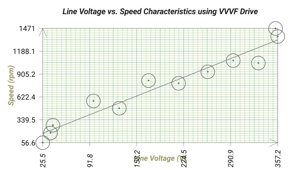
- To plot line voltage (VL) vs. speed (N) characteristics
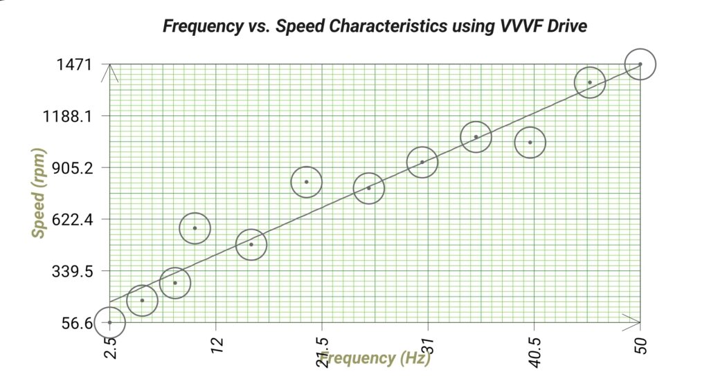
- To plot frequency (f) vs. speed (N) characteristics
Theory:
VVVF stands for Variable Voltage Variable Frequency. VVVF Speed Control method is widely used method for Induction Motor.
As we know that synchronous speed of machine is given as
Ns (rpm) = 120f/P …………………………………(1) where f is frequency and P is number of pole.
Thus if we can change the frequency f then it is possible to change the speed of induction motor. Now frequency of power supply can easily be varied using power electronics devices like inverter. The inverter converts DC power into AC power and feeds to induction motor. Inverter output may be either constant voltage variable frequency or variable voltage variable frequency. Which one to choose?
Suppose inverter output is constant voltage but variable frequency. Thus we can write V = Constant but f = Variable.
The relationship between voltage V and frequency f is well known and can be written as
V = 4.44fNØ ……………………………….(2)
where N is number of turns per phase and Ø is resultant air gap flux.
Suppose we want to reduce the speed of induction motor. For this, obviously we will have to reduce the frequency f while keeping V constant as per (1). But from (2),
Ø = V / (4.44fN) …………………………..(3)
Air gap flux Ø will increase which may cause machine core to saturate which is not desirable. Thus the concept of speed control with constant voltage variable frequency cannot be adopted.
But from (3), it is possible to achieve constant flux Ø by maintaining (V/f) constant. This allows us to change voltage and frequency simultaneously to have speed control while maintaining constant air gap flux. This is the basic concept behind VVVF speed control of induction motor.
“In VVVF speed control, motor stator supply as well as frequency is varied such that ratio (V/f) is constant.”
Block Diagram of VVVF Drive:
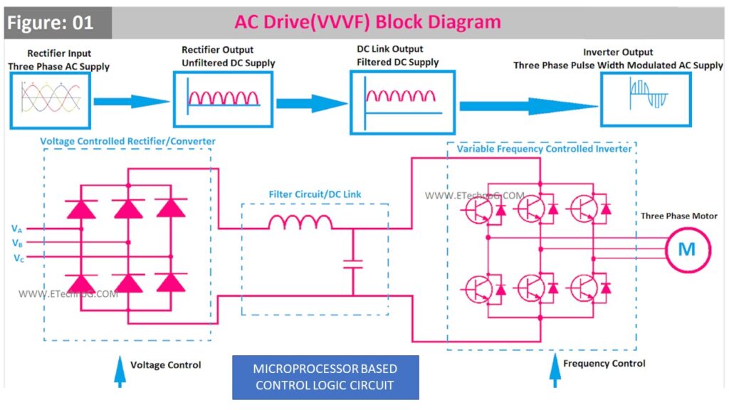
Working Principle of VVVF Drive:
VVVF Drive system has main three blocks or parts,
- Voltage Controlled Rectifier or AC-DC Converter
- DC Link or Filter
- Frequency Controlled Inverter
Rectifier/Converter
The main function of a rectifier circuit is to convert the alternating current(AC) into direct current(DC). In this drive system, the rectifier circuit takes the three-phase AC supply as input and gives DC supply as output. Here, we used the term voltage-controlled rectifier because the rectifier not only converts the AC into DC in fact, it controls or changes the voltage level with the help of a logic control circuit. This converter or rectifier circuit is generally built with diodes, SCR, etc. Varying the gate pulse to the SCR can vary the voltage and current conduction.
Filter Circuit or DC Link
It is built with either a parallel capacitor or a series inductor or a combination of both inductor and capacitor. The function of this circuit is to filtrate the impure DC supply from the rectifier circuit and make a link between the rectifier circuit and the inverter circuit.
Inverter
Here, the inverter circuit converts the DC supply into a variable three-phase AC supply. It basically works with the pulse width modulation (PWM) technique.
The variable frequency can vary the speed of the induction motor. This inverter circuit is generally built with MOSFETs or IGBTs or any high-speed switching semiconductor device.
Here turning on or off the individual components can vary the frequency of the supply. This inverter circuit is also controlled by the logic control circuit which is mostly built with a microprocessor.
In the block diagram of the VVVF Drive or AC drive system, each block is explained with waveforms.
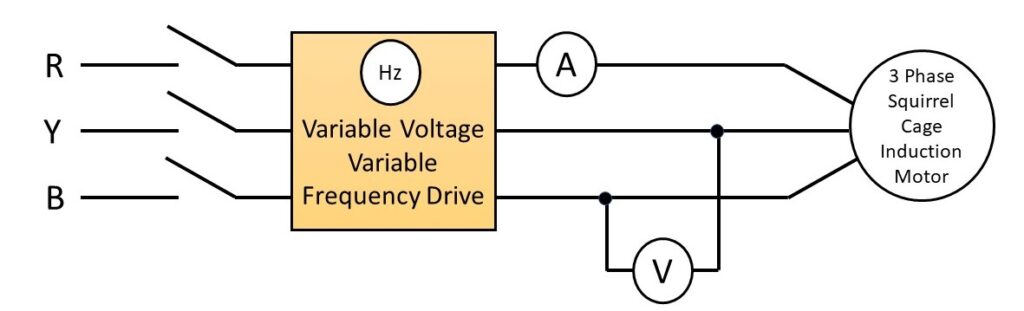
Circuit Diagram:
Observation Table:
| Sl. No. | Line Voltage (VL) | Frequency (Hz) | Speed (rpm) |
| 1. | 25.5 | 2.46 | 56.6 |
| 2. | 36.5 | 5.39 | 178.0 |
| 3. | 40.0 | 8.34 | 274.6 |
| 4. | 97.2 | 10.10 | 573.9 |
| 5. | 133.8 | 15.16 | 484.0 |
| 6. | 174.9 | 20.10 | 826.5 |
| 7. | 217.5 | 25.71 | 792.4 |
| 8. | 258.6 | 30.49 | 935.8 |
| 9. | 294.6 | 35.29 | 1074.0 |
| 10. | 330.3 | 40.14 | 1044.0 |
| 11. | 357.2 | 45.51 | 1371.0 |
| 12. | 354.2 | 50.00 | 1471.0 |
Apparatus Used:
| Sl. No. | Name of the Apparatus | Specification | Quantity | Maker’s Name |
| 1. | Panel for Speed Control of Induction Motor by VVVF Controller | 415 V, 3-ph Input | 1 | Tech Track |
| 2. | VVVF Drive | Input: AC 3ph, 380-480 V AC, 3.5 A, 48-63 Hz, Output: AC 3ph, 0-Input V AC, 2.5 A, 0-600 Hz, Motor rating: 0.75 kW | 1 | CG Power and Industrial Solutions Ltd. |
| 3. | 3ph Squirrel Cage Induction Motor | 1HP, 1440 rpm, 1.5 A, 415 V, 50 Hz | 1 | Tech Track |
| 4. | Digital Multimeter as Voltmeter | 0-750 V AC, 0-1000 V DC, 0-10 A | 1 | Akademika |
| 5. | Tachometer | Digital, Non contact type | 1 | Metrix+ |
Graph:
Remarks:
Views: 595