Experiment No.: 4 (A)
Experiment Name:
Measure the open circuit voltage ratio of the 3-ph slip ring induction motor.
Objective:
To measure the open circuit voltage ratio of the 3-ph slip ring induction motor.
Theory:
This test is the routine type test of slip ring induction motor only as per IS:325. This test is applicable only in case of 3-phase slip ring induction motor because in case of squirrel cage induction motor there are no connection between output winding. This test is to be performed to know the open circuit voltage ratio of the stator and rotor winding of slip ring induction motor.
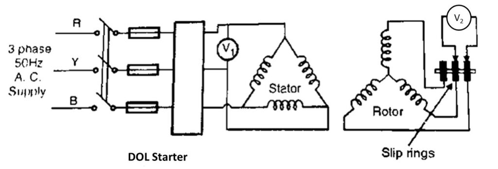
This test is carried out to find out the voltage ratio or turns ratio of the primary and secondary winding. The rated voltage is given to the stator of the slip ring induction motor and voltmeter is to be connected accross the sliprings. As we have to measure the open circuit voltage ratio, so, in this test rotor circuit is to be kept open by removing the external rotor resistance.
The voltage across the slip ring is V2 and the voltage across the stator winding is V1. The measured voltage is line voltage, so we have to devide the value by √3, to get the value in phase voltage.
Voltage ratio = Primary voltage or stator voltage per phase (V1) / Secondary voltage or rotor voltage per phase (V2)
Circuit Diagram:

Observation Table:
| Sl. No. | Stator Voltage per phase (V1/√3) (Volt) | Rotor Voltage (V2/√3) (Volt) | Voltage Ratio (V1/V2) | |
| 1. | VRY | |||
| 2. | VYB | |||
| 3. | VBR |
Apparatus Used:
| Sl. No. | Name of the apparatus | Specification | Quantity | Maker’s Name |
| 1. | 3 Phase Slip Ring Induction Motor with rotor resistance starter | 3 HP, 3 ph, 415 V, Wound rotor type | 1 | M.E.W. |
| 2. | Digital Multimeter as voltmeter | 0-750V AC, 0-1000 V DC, 0-10 A | 1 | Akademika |
Remarks:
Related posts:
Direct Loading Test on 3-ph Alternator to Determine the Regulation and Efficiency
Identification of Different Parts for a Three Phase Induction Motor (along with Function and Materia...
Direct Load Test on the 3-ph Squirrel Cage Induction Motor and Plotting the i) Efficiency Versus Out...
Dismantling and Reassembling of Single Phase Motors Used for Ceiling Fan
Views: 22
