Experiment No.: 6
Experiment Name:
Use CRO for the measurement of voltage, frequency, phase angle
Objective:
To use CRO for the measurement of voltage, frequency, phase angle.
Theory:
CRO: The CRO stands for a cathode ray oscilloscope. It is typically divided into four sections which are display, vertical controllers, horizontal controllers, and Triggers. Most of the oscilloscopes are used the probes and they are used for the input of any instrument. We can analyze the waveform by plotting amplitude along with the x-axis and y-axis. The applications of CRO’s mainly involve in the radio, TV receivers, also in laboratory work involving research and design. In modern electronics, the CRO plays an important role in the electronic circuits.
Applications of CRO:
- Voltage measurement
- Current measurement
- Examination of waveform
- Measurement of phase angle and frequency
Measurement of Voltage:
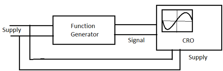
To measure the voltage at first the sinusoidal signal is fed to the CRO channel- 1from Function Generator. Then we set particular wave shaped amplitude by setting the fine frequency knob. Then we count the number of division of the peak-to peak voltage (VPP) and calculated the same by multiplying no. of division and voltage/division. Thus we calculate the Vrms and Vavg and observed that the reading is almost same with the observed value.
Measurement of Frequency:
To measure the frequency of an unknown signal at first we have to set up just like before. Then we have to count the no. of division and time/division (shown by CRO). Then reciprocating the time period we can get frequency.
Measurement of Phase Angle:
To measure the Phase Angle, we have to measure the number of units of angular measure between the point on the wave and reference point. It is important to note that the reference point can be present on the same waveform or another wave.
Block Diagram:
Observation Table:
| Sl. No. | Observed Waveform | Measured Voltage (Vpp) | Measured Voltage (Vrms) | Measured Voltage (Vavg) | Time Period | Frequency | Phase Angle from reference |
| 1. | Sinusoidal [Observerd Value] | 3.062 V | 1.604 V | 1.162 V | 16.85 ms | 59.35 Hz | 90° |
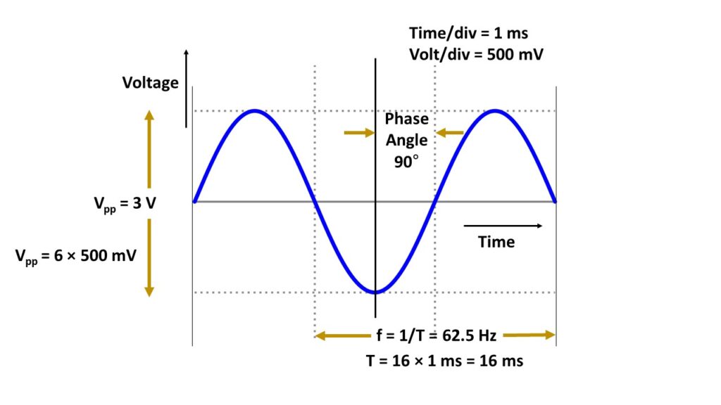
[Calculated Value] | 6 div×500 mV/div = 3 V | 1.5/√2 = 1.0606 V | 2×1.5/π = 0.954 V | 16 div×1ms = 16 ms | 62.5 Hz | 90° |
Apparatus Used:
| Sl No. | Name of the Apparatus | Specification | Quantity | Maker’s name |
| 1. | CRO | Dual beam, 200MHz, digital | 1 | Akademika |
| 2. | BNC Probe | Coaxial | 1 | Akademika |
| 3. | Function generator | Digital | 1 | Akademika |
Waveform:
Remarks:
The observed values and calculated values are almost same. This difference is due to impurities into the signal. Rectifying this error the voltage, frequency and phase angle are measured successfully.
Views: 548