Experiment No.: 4(A)
Experiment Name:
Realization of Half Adder, Full Adder
Objective: To implement the circuit and verify the circuit with truth table of
- Half adder
- Full adder
Theory:
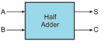
Half adder: The simplest combinational circuit performs the arithmetic addition of two binary digit is called Half Adder. The half adder has 2 input and 2 output i.e. Sum (S) and Carry (C).
Block Diagram:

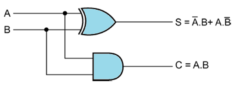
Circuit Diagram of Half Adder using Logic Gates:
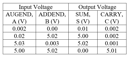
Observation Table:
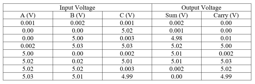
Full Adder: The simplest combinational circuit that performs the arithmetic operation of three binary digit is called Full Adder. It has 3 input and 2 output.
Block Diagram:

Truth Table of Full Adder:


Circuit Diagram of Full Adder using Logic Gates:

Observation Table:
Apparatus Used:
| Sl No. | Name of Apparatus | Quantity | Specification | Makers name |
| 1. | Logic Gate Trainer Kit | 1 | IC 7432, IC 7408, IC 7404, IC 7400, IC 7402 | Salicon |
| 2. | Connecting Probes | As required | ||
| 3. | Digital Multimeter | 1 | 0-1000 V DC, 0-750 V AC, 0-10 A | Akademika |
Remarks: The half adder and full adder circuits are implemented and verified the truth table.
Views: 436