Experiment No. : 6
Experiment Name :
Test the PN junction Diodes using Digital Multimeter and find out their V-I characteristics in Forward Biased Circuit.
Objective :
- To test the PN junction diode using digital multimeter.
- To find out the V-I characteristics in Forword Biased Circuit.
Theory :
A diode is a two-terminal electronic component that conducts current primarily in one direction (asymmetric conductance); it has low (ideally zero) resistance in one direction, and high (ideally infinite) resistance in the other. A diode vacuum tube or thermionic diode is a vacuum tube with two electrodes, a heated cathode and a plate, in which electrons can flow in only one direction, from cathode to plate.
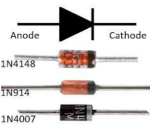
If +ve terminal of the input supply is connected to anode (P-side) and –ve terminal of the input supply is connected to cathode (N- side) then diode is said to be forward biased. In this condition the height of the potential barrier at the junction is lowered by an amount equal to given forward biasing voltage. Both the holes from p-side and electrons from n-side cross the junction simultaneously and constitute a forward current (injected minority current – due to holes crossing the junction and entering N-side of the diode, due to electrons crossing the junction and entering P-side of the diode). Assuming current flowing through the diode to be very large, the diode can be approximated as short-circuited switch.
A multimeter’s Diode Test mode produces a small voltage between test leads. The multimeter then displays the voltage drop when the test leads are connected across a diode when forward-biased.
Diode test analysis
- A good forward-biased diode displays a voltage drop ranging from 0.5 to 0.8 volts for the most commonly used silicon diodes. Some germanium diodes have a voltage drop ranging from 0.2 to 0.3 V.
- The multimeter displays OL when a good diode is reverse-biased. The OL reading indicates the diode is functioning as an open switch.
- A bad (opened) diode does not allow current to flow in either direction. A multimeter will display OL in both directions when the diode is opened.
- A shorted diode has the same voltage drop reading (approximately 0.4 V) in both directions
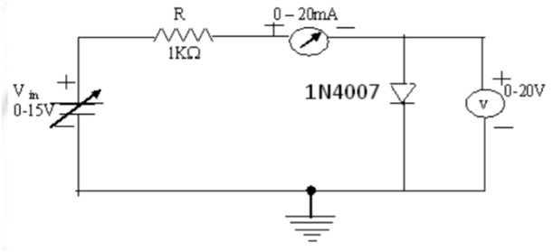
Circuit Diagram:
Observation Table:
| Sl.No. | Forward Voltage across the Diode (V) | Forward Current through the Diode (mA) |
| 1. | 0.20 | 0 |
| 2. | 0.40 | 0 |
| 3. | 0.55 | 0.2 |
| 4. | 0.62 | 1.1 |
| 5. | 0.65 | 2.0 |
| 6. | 0.67 | 3.0 |
| 7. | 0.68 | 4.2 |
| 8. | 0.70 | 6.3 |
| 9. | 0.74 | 16.2 |
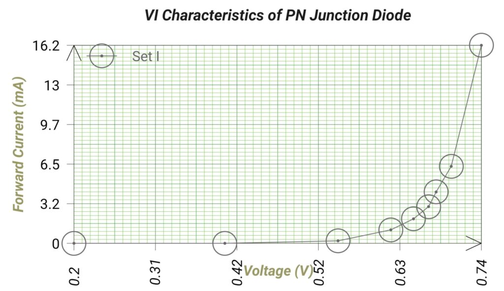
Graph:
Apparatus Used:
| Sl. No. | Name of the Apparatus | Quantity | Specification | Maker’s Name |
| 1. | Diode & Zener Diode Characteristics Trainer Kit | 1 | Diode 1N4007 | M.E.W. |
| 2. | Digital Multimeter | 1 | 0-10 MΩ, 0-750 V, 0-10 A | Akademika |
Remarks:
The forward characteristics of the pn junction diode is plotted on graph and the knee voltage is found out. The forward voltage is measured using digital multimeter.
Related posts:
Measurement of Voltage, Current, Power and Power Factor in a R-L Series Circuit
Identification of Various Active and Passive Electronic Components in a Given Circuit
Identification of 3 terminal of a Transistor and to calculate Gain in CE Mode
Identification of Different Parts of a Single-Phase Transformer
Views: 882