Experiment No. : 1
Experiment Name:
Measurement of Voltage, Current and Power in a Single-Phase Circuit with Resistive Load.
Objective:
To measure the voltage, current and power in a single-phase circuit with Resistive load.
Theory:
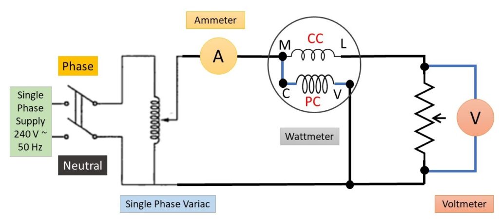
As per shown circuit diagram, we have used a rheostat as resistive load. An MI type ammeter is connected in series with the rheostat to measure the current flowing through it. We have selected the ammeter according to the load current. An MI type voltmeter is connected across the load to measure the voltage across it. To measure the power drawn by the load we have connected a wattmeter. We have selected the Wattmeter and Voltmeter as per supply voltage and current rating of the load.
In Wattmeter, the multiplying factor is given by,

In our case,
(i) MF= (150×5×1)/750 = 1 [When supply voltage is 100 V]
(ii) MF= (300×5×1)/750 = 2 [When supply voltage is 200 V]
So, we have to multiply 1 and 2 with the reading taken from the Wattmeter in Sl. No. 1 and 2 respectively as shown in observation table.
Circuit Diagram:
Observation Table:
| Sl. No. | Resistance (Ohm) | Voltage (V) | Current (A) | Power (W) |
| 1. | 100 | 100 | ||
| 2. | 100 | 200 |
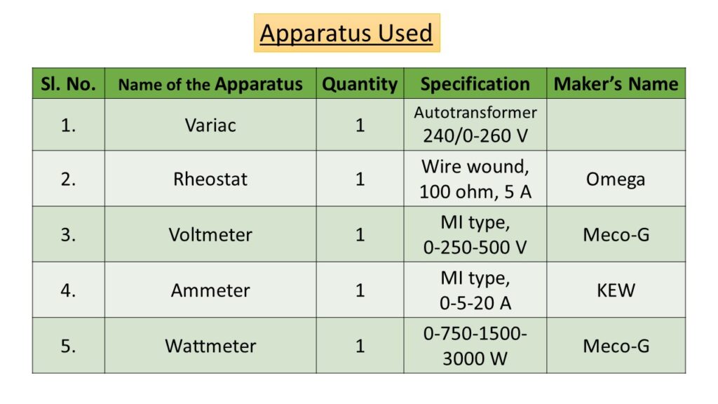
Apparatus Used:
Remarks:
- We should not touch the rheostat coil during and after the test, because it will dissipate a good amount of heat.
- The resistance of the rheostat should be measured after disconnecting from the supply without changing its value through jockey.
Related posts:
Use of LCR-Q meter to measure the value of a given Capacitor and Inductor
Identification of Various Active and Passive Electronic Components in a Given Circuit
Measurement of Voltage, Current and Power and Power Factor in a R-L series circuit
Identification of 3 terminal of a Transistor and to calculate Gain in CE Mode
Views: 887
Khub valo.
Pronam nio maa. Asirbaad koro jeno evabei egiye jete pari.
Awesome. Have a Great Journey
Thank you. Have a great day.