Experiment No.: 7
Experiment Name:
Measurement of Voltage, Current and Power and Power Factor in a R-L series circuit.
Objective:
To measure the voltage, current, power and power factor in a R-L series circuit.
Theory:
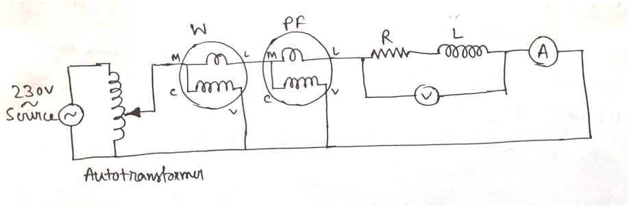
As per shown circuit diagram, we have used a 200 Watt incandescent lamp as resistive load (R) connected in series with a ballast of fluorescent lamp as an inductive load (L) as resistive load.
An MI type ammeter is connected in series with the load to measure the current flowing through it. We have selected the ammeter according to the load current. An MI type voltmeter is connected across the load to measure the voltage across it. To measure the power drawn by the load we have connected a wattmeter. And to measure the load power factor we have used a Power Factor meter.
In Wattmeter, the multiplying factor (MF) is given by,

In our case, MF= (300×10×1)/1500 = 2
So, we have to multiply 4 with the reading taken from the Wattmeter.
Circuit Diagram:
Observation Table:
| Sl. No. | Resistance (Ω) | Inductance (mH) | Voltage (V) | Current (A) | Power (W) | Power Factor (cos φ) |
Apparatus Used:
| Sl. No. | Name of the Apparatus | Quantity | Specification | Maker’s Name |
| 1. | Incandescent Lamp | 1 | 200 W, 240 V | Phillips |
| 2. | Choke Coil | 1 | 40 W, 240 V | Intex |
| 3. | Single Phase Wattmeter | 1 | 0-750-1500-3000 W, 300 V, 10 A, EDM type | MECO-G |
| 4. | Single Phase Power Factor Meter | 1 | 0.5 lag – 1 – 0.5 lead | MECO-G |
| 5. | Voltmeter | 1 | 0 – 300 – 600 V, MI type | MECO-G |
| 6. | Ammeter | 1 | 0 – 5 – 10 A, MI type | K.E.W. |
| 7. | Single Phase Variac | 1 | 240 V / 0 – 270 V |
Remarks:
The reading of wattmeter is too low to read accurately.
Related posts:
Sample Question and Answer for FEEE Lab Viva-voce
Use of LCR-Q meter to measure the value of a given Capacitor and Inductor
Test the PN junction Diodes using Digital Multimeter and find out their V-I characteristics in Forwa...
Measurement of Voltage, Current and Power in a Single Phase Circuit with Resistive Load
Views: 181