Experiment No.: 05
Experiment Name:
Prepare wiring installation on a board showing control of one lamp, one fan and one socket from one switch board using Batten Wiring System.
Objective:
- To prepare a batten wiring installation on a wiring board.
- To control one lamp, one fan and one socket from one switch board.
- To learn the proper connection of phase, neutral and earth wires.
- To test the working of each load separately.
Theory:
Batten wiring is a wiring system in which insulated wires are fixed on a batten with the help of clips. In this experiment, one lamp, one fan and one socket are connected to a single switch board.
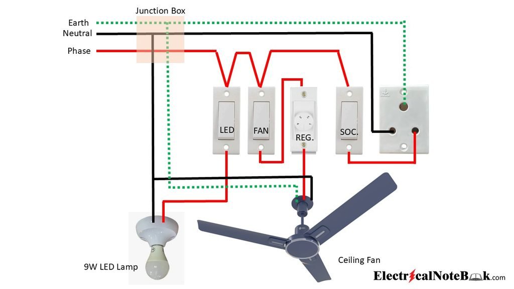
The phase wire is connected to the switches. The lamp is controlled by one switch. The fan is controlled by another switch through a fan regulator. The socket is controlled by a separate switch. The neutral wire is connected to the lamp, fan and socket. The earth wire is connected to the earth terminal of the socket for safety.
Advantages of Batten Wiring:
- It is simple and easy to install.
- It gives a neat appearance.
- Fault finding is easy.
- Repair and maintenance are easy.
- It is suitable for temporary and small installations.
Tools Used:
| Sl. No. | Tools Required | Quantity |
|---|---|---|
| 1 | Insulated Screwdriver | 1 |
| 2 | Line Tester | 1 |
| 3 | Combination Plier | 1 |
| 4 | Cutting Plier | 1 |
| 5 | Wire Stripper | 1 |
| 6 | Hammer | 1 |
| 7 | Hand saw | 1 |
| 8 | Measuring Tape | 1 |
| 9 | Digital Multimeter | 1 |
Wiring Diagram:
Materials Required:
ESTIMATE
| Sl. No. | Particulars | Specification | Quantity |
|---|---|---|---|
| 1 | PVC/Wooden Batten | Suitable size | As Required |
| 2 | Switch Board | 6″ X 4″ PVC/Wooden | 1 |
| 3 | One-Way Switch | 6A, 240V | 3 |
| 4 | Fan Regulator | Smooth control type | 1 |
| 5 | Lamp Holder | B22, Pendent Type Holder | 1 |
| 6 | LED/Lamp | 9W, 230 V | 1 |
| 7 | Ceiling Fan | Sweep:1200mm, 230 V | 1 |
| 8 | 3-Pin Socket | 6A, 240V | 1 |
| 9 | PVC/Wooden Bends | Suitable size | As Required |
| 10 | PVC/ Aluminum Saddle | Suitable size | As Required |
| 11 | Cable | 1.0 sq.mm, 1100V grade, PVC insulated, Copper stranded | Red & Black 2m each |
| 12 | Cable | 0.5 sq.mm, 1100V grade, PVC insulated, Copper stranded | Green 2m |
| 13 | Junction Box | PVC/Wooden | 1 |
| 14 | Mounting Screws | 3/4″, 1.0″, Flat headed, All thread | As required |
*The material list follows the standard setup used for this practical.
Procedure:
- Collect all the required tools and materials.
- Check the condition of all electrical accessories.
- Mark the positions of the switch board, lamp holder, fan, socket and batten on the wiring board.
- Fix the batten properly on the board.
- Fix the switch board, lamp holder, fan and socket in their proper positions.
- Fix the wires on the batten using suitable clips.
- Connect the incoming phase wire to the common terminal of the switch board.
- Connect the first switch to the lamp holder.
- Connect the second switch to the fan regulator and then to the fan.
- Connect the third switch to the socket.
- Connect the neutral wire to the lamp, fan and socket.
- Connect the earth wire to the earth terminal of the socket and fan body.
- Check all connections and tighten the terminals properly.
- Check the wiring for any short circuit or wrong connection.
- Give the supply only after completing all safety checks.
- Operate each switch separately and check the lamp, fan and socket.
- Check the fan speed using the fan regulator.
Observation Table:
| Load | Test | Result |
|---|---|---|
| Lamp | ON/OFF by switch | OK |
| Fan | ON/OFF and speed controlled by regulator | OK |
| Socket | Supply available, phase detected on right side pin | OK |
Precautions:
- Switch OFF the supply before making any connection.
- Use insulated tools for electrical work.
- Use wires of suitable size and proper insulation.
- Tighten all terminals properly.
- The phase wire must be connected through the switches.
- Proper earthing must be provided to the socket.
- Do not touch any live conductor with bare hands.
- Check all connections before giving supply.
- Keep the wiring neat and properly fixed on the batten.
- Do not give supply if any loose or exposed connection is found.
Conclusion:
By performing this experiment, we learned how to prepare a batten wiring installation on a board and control one lamp, one fan and one socket from a single switch board. The lamp, fan and socket were tested separately and found working properly.
Viva Questions:
- What is batten wiring?
- How many switches are used in this experiment?
- Which switch controls the lamp?
- Why is a fan regulator used?
- Which wire is connected through the switches?
- Why is the earth wire connected to the socket?
- What is the function of the socket switch?
- What is the function of the neutral wire?
- Why are clips used in batten wiring?
- What should be checked before giving supply?
Views: 1