Experiment No.: 2
Experiment Name:
Select the Electric Wire Using Measuring and Testing Instruments for Particular Applications
Objective:
To identify, measure, test, and select the appropriate electric wire for different electrical applications using measuring and testing instruments.
Theory:
The correct selection of electric wire is essential for the safe and efficient operation of any electrical installation. An undersized wire may overheat, cause voltage drop, or even lead to fire hazards. Therefore, before using a wire, its size, continuity, resistance, and insulation condition should be verified.
The conductor diameter is measured using a SWG Measurement Tool, electrical continuity is checked with a Digital Multimeter, and insulation quality is tested using a Megger (Insulation Tester).
The cross-sectional area of a solid conductor is calculated by:
A=4πd2
Where:
- = Cross-sectional area (mm²)
- = Diameter of the conductor (mm)
Instruments Used:
| Instrument | Purpose |
|---|---|
| SWG Measurement Tool | Measures conductor diameter |
| Digital Multimeter | Checks continuity and resistance |
| Hand-driven Megger (500 V) | Tests insulation resistance |
Wire Selection Chart:
| Application | Recommended Wire Size |
|---|---|
| LED Light | 1.0 mm² |
| Fan | 1.5 mm² |
| 6A Socket | 1.5 mm² |
| 16A Socket | 2.5 mm² |
| Geyser (3000 W) | 4.0 mm² |
Procedure:
- Switch OFF the power supply before handling any wire.
- Remove a small portion of insulation using a wire stripper.
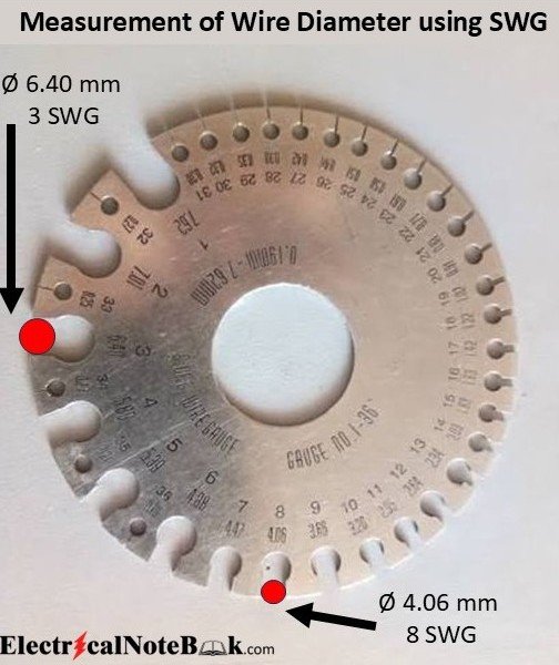
- Measure the conductor diameter with a SWG (Standard Wire Guage) Measurement Tool.
- Calculate the cross-sectional area if required.
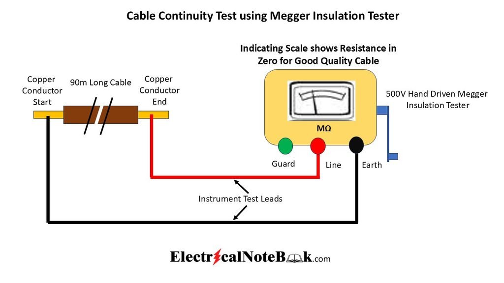
- Set the Digital Multimeter to Continuity Mode and test the wire.
- Measure resistance if necessary.
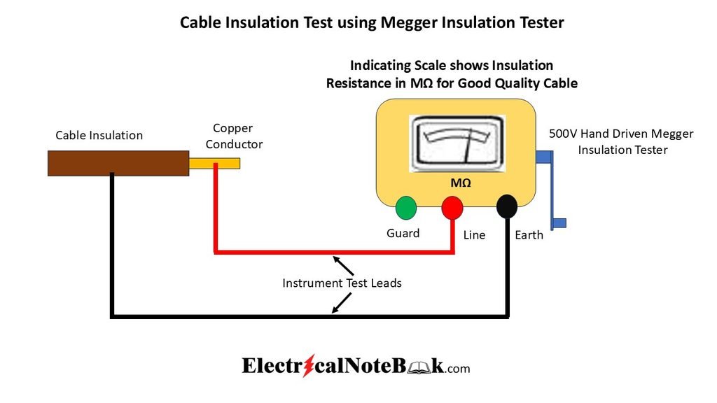
- Use a 500 V Megger to check insulation resistance.
- Compare the measured wire size with the required application.
- Select the suitable wire and record the observations.
Circuit Diagram for Continuity Test:
Measurement of Wire Diameter using SWG:
Circuit Diagram for Insulation Resistance Test:
Observation Table:
| Wire Size | Measured Diameter | SWG | Continuity | Insulation | Suitable Application |
|---|---|---|---|---|---|
| 1.0 mm² | 1.13 mm | 19 | Pass | Good | Lighting |
| 1.5 mm² | 1.38 mm | 17 | Pass | Good | Fan |
| 2.5 mm² | 1.78 mm | 14 | Pass | Good | Socket |
| 4.0 mm² | 2.26 mm | 12 | Pass | Good | Heavy Load |
Precautions:
- Ensure the circuit is de-energized before testing.
- Never use a Vernier Caliper on a live conductor.
- Discharge the cable before using a Megger.
- Use insulated tools and wear safety gloves.
- Replace damaged or poorly insulated wires immediately.
Conclusion:
The electric wires were successfully measured and tested using a SWG Measurement Tool, Digital Multimeter, and Megger. Based on the measured size and test results, the appropriate wire for each electrical application was selected.
Viva Questions:
- Why is wire size important in electrical wiring?
- Which instrument is used to measure conductor diameter?
- What is the purpose of a continuity test?
- Why is insulation resistance tested?
- Which wire size is commonly used for a 6A socket?
- What happens if an undersized wire carries excessive current?
- What is the formula for calculating the cross-sectional area of a conductor?
- Why should the power supply be switched OFF before testing?
- Full form of SWG?
- What is the purpose of insulation resistance test?
Views: 283
Related posts:

100 One Liners Q&A on Building Electrifications

Prepare Series Testing Board for Testing Fan or Other Electrical Gadgets
Prepare wiring installation on a board showing control of one lamp, one fan and one socket from one ...