Experiment No.: 3
Experiement Name:
Construction of full-wave rectifier circuit & draw input, output waveforms – with filters and
without filters.
Objective:
- To construct full-wave rectifier circuit.
- To draw input, output waveforms – with filters and without filters.
Theory:
The conversion of AC into DC is called Rectification. Electronic devices can convert AC power into DC power with high efficiency.
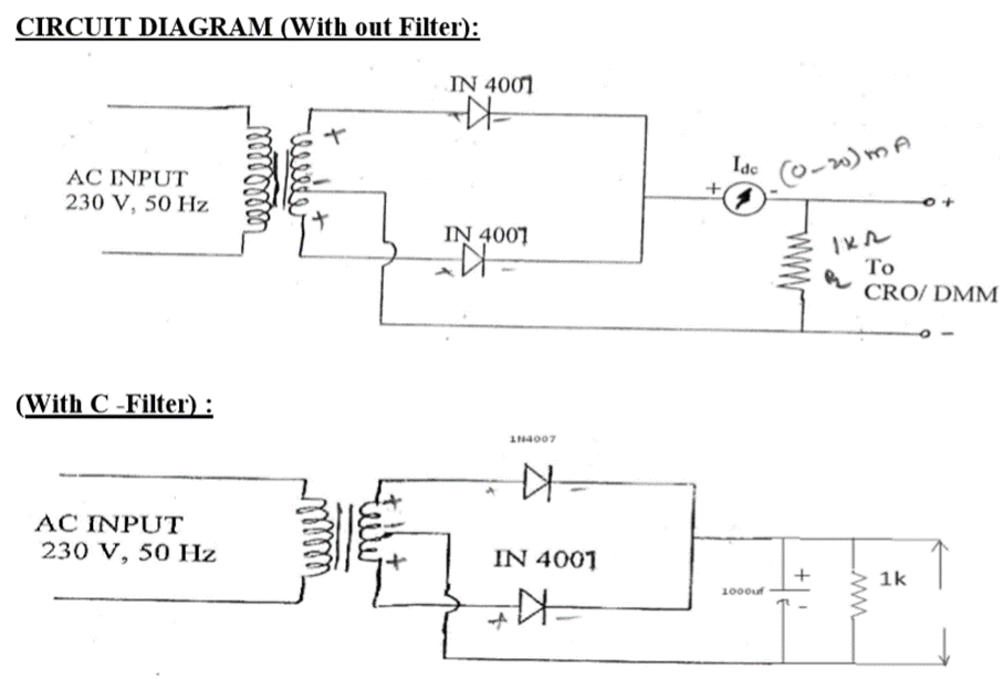
Full Wave Rectifier:
The full-wave rectifier consists of a center-tap transformer, which results in equal voltages above and below the center-tap. During the positive half cycle, a positive voltage appears at the anode of D1 while a negative voltage appears at the anode of D2. Due to this diode D1 is forward biased it results in a current Id1 through the load R. During the negative half cycle, a positive voltage appears at the anode of D2 and hence it is forward biased. Resulting in a current Id2 through the load at the same instant a negative voltage appears at the anode of D1 thus reverse biasing it and hence it doesn’t conduct.
Procedure:
- Make connections as per the Circuit Diagram.
- Note down the AC and DC Voltages and Currents without Filter and with Load.
- And again observe the AC and DC Voltages and Currents with Filter and with load.
- Observe the Voltage across the secondary of the Transformer (i.e. Vrms).
Observation Table: Vac = 9.25 V (Voltage across the secondary of the transformer)
| Condition | Vac | Vdc | Vm | R |
| Without Filter | 9.25 V | 7.36 V | 13.12 V | 1 kOhm |
| Condition | Vac | Vdc | Vm | C | R |
| With C-Filter | 9.27 | 8.56 V | 13.42 V | 100 µF | 1 kOhm |
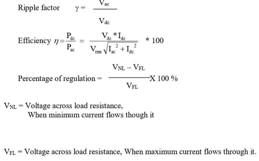
Calculation:
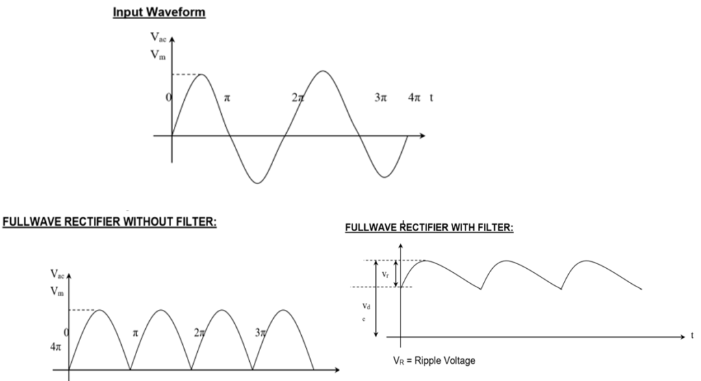
Observed waveform:
Result:
| Parameter | Without Filter | With C-Filter |
| Ripple Factor | 1.25 | 1.08 |
| Efficiency ((dc power/ac power)x100 %) | 63.3 % | 85.26 % |
Apparatus Used:
| Sl No. | Name of Apparatus | Quantity | Specification | Makers name |
| 1. | Half wave & full wave rectifier trainer kit | 1 | 230 V, 50 Hz input, 1N4007 Diodes | M.E.W. |
| 2. | Digital Multimeter | 1 | 0-750 V AC, 0-1000 V DC, 0-10 A | Akademika |
| 3. | Digital Storage Oscilloscope | 1 | 100 MHz | Akademika |
Remarks: The input and output waveforms are visulalised in CRO perfectly.
Views: 485