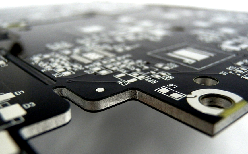
In high-power electronic systems and high-temperature environments, the limitations of traditional FR4 substrate material in heat dissipation have become increasingly evident. Excessive heat generated by components can lead to elevated junction temperatures, performance degradation, shortened lifespan, and even safety risks.
Metal Core PCBs (MCPCBs), with their unique structure of metal base + thermally conductive dielectric layer + circuit layer, can improve heat dissipation performance by several times—or even an order of magnitude. As a result, they have become a core solution in applications such as LED lighting, automotive electronics, power supplies, and industrial control systems.
Unlike conventional FR-4 PCBs, MCPCB design is not only about standard routing rules. It must also focus on three critical aspects:
- Thermal optimization
- Electrical insulation
- Thermal stress management
A successful design must balance electrical performance with mechanical reliability.
This guide provides a comprehensive overview of MCPCB design—from fundamental concepts and design workflows to key considerations, material selection, common pitfalls, and real-world engineering practices. Whether you are a beginner, DIY enthusiast, hardware engineer, or industry professional, this article will help you avoid design mistakes and build stable, high-performance MCPCBs.
Core Structure of Metal Core PCB
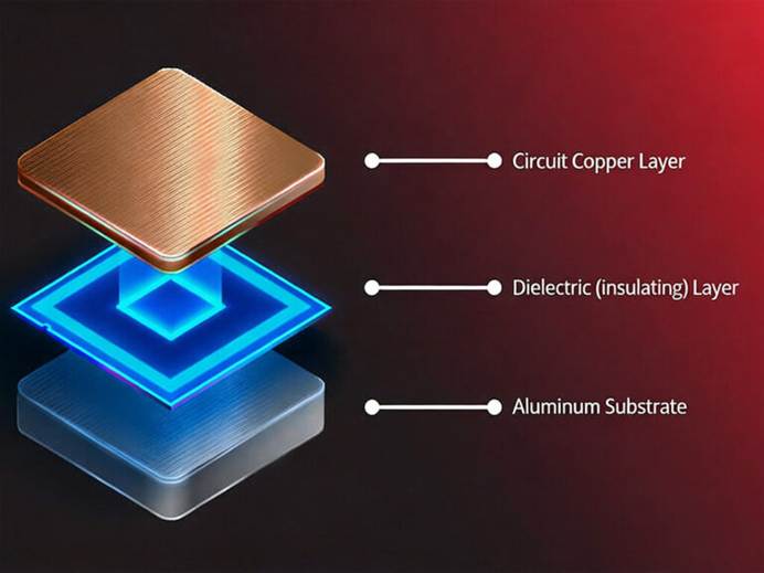
The core advantage of MCPCBs comes from their unique three-layer structure, which differs significantly from the fiberglass-epoxy composition of FR-4 boards. MCPCBs are specifically engineered to optimize both heat dissipation and insulation.
From top to bottom, the structure includes:
Circuit Layer (Copper Layer)
Similar to standard PCBs, this layer is used to form conductive traces and pads for component mounting.
- Typical copper thickness: 1 oz to 6 oz
- Function: electrical conduction and auxiliary heat spreading
Thermally Conductive Dielectric Layer (Core Functional Layer)
This is the “heart” of the MCPCB, typically with a thickness of 50–150 μm. It is made of materials such as:
- Epoxy resin with ceramic fillers
- High thermal conductivity polymers
- Polyimide
Key functions:
- Electrically isolate the circuit layer from the metal base (prevent short circuits)
- Efficiently transfer heat from the circuit layer to the metal substrate
This layer plays a decisive role in both thermal performance and insulation reliability.
Metal Base Layer (Primary Heat Dissipation Layer)
This is the defining feature of MCPCBs. The metal base serves as the structural support and the main heat dissipation path.
Common materials include:
- Aluminum
- Copper
- Copper-aluminum composites
Its function is to:
- Absorb heat from the dielectric layer
- Rapidly spread and dissipate heat to the environment or external heat sinks
Common Types of MCPCBs
Aluminum-Based MCPCB (Al-MCPCB)
- Most widely used (>80% of the market)
- Thermal conductivity: ~1–3 W/(m·K)
- Advantages: lightweight, cost-effective, easy to process
- Applications: LED lighting, consumer electronics, standard industrial control
Copper-Based MCPCB (Cu-MCPCB)
- Thermal conductivity: >380 W/(m·K)
- Much higher than aluminum (~100×)
- Better CTE match with silicon chips → improved reliability
Advantages:
- Superior heat dissipation
- Reduced thermal stress
Disadvantages:
- Higher cost
- Heavier weight
- More complex processing
Applications:
- High-power LEDs
- Automotive power systems
- Radar and IGBT modules
Copper-Aluminum Composite MCPCB
Combines advantages of both materials:
- Copper layer for heat transfer
- Aluminum layer for weight reduction and cost control
Applications:
- Automotive electronics
- Drone power modules
Steel-Based MCPCB
- Extremely high mechanical strength
- Excellent vibration resistance
- Poor thermal conductivity
Applications:
- Heavy industrial equipment
- Military auxiliary circuits
Specialized Design Guidelines for Different Application Scenarios
Scenario 1: LED Lighting (Most common, over 60% of MCPCB usage)
Core Requirements:
Uniform heat dissipation, cost-effective, outdoor durability, ease of mass production. Mainly used in LED streetlights, wall washers, floodlights, and linear lights.
Material Selection:
- Metal Substrate: Aluminum is preferred due to its balance of cost, weight, and thermal performance.
- Copper foil: 1–2oz depending on current requirements.
- Thermal insulation layer: Epoxy or ceramic-filled epoxy, thickness 50–100μm for standard power LEDs.
Layout Guidelines:
- Place high-power LED chips centrally on the metal core to ensure uniform heat spreading.
- Keep spacing between high-power devices ≥8mm to prevent localized overheating.
- Position drivers and heat-sensitive components away from LEDs, preferably near PCB edges for better heat dissipation.
Routing Guidelines:
- Use wide traces for LED power lines. Prefer continuous copper planes for main current paths.
- Avoid routing small signal lines under high-power LEDs.
- Ensure creepage and clearance meet safety requirements, typically adding 20% margin due to thin insulation layer.
Heat Management:
- Add dense thermal vias under LEDs to connect copper pads with the metal substrate.
- Use copper pour and thermal pads to increase conduction to the metal core.
- For high-power LEDs PCB projects (>50W), consider auxiliary heat sinks attached to the metal base with thermal paste.
Scenario 2: Automotive Electronics
Core Requirements:
High reliability under wide temperature ranges (-40°C to +105°C), vibration resistance, compliance with automotive safety standards (e.g., ISO 26262, UL94V-0).
Material Selection:
- Metal substrate: Copper or copper-aluminum composite for superior thermal conductivity and reduced CTE mismatch with silicon chips.
- Thermal insulation layer: High thermal conductivity ceramic-filled epoxy or polyimide, 75–150μm thickness.
- Copper foil: 2–3oz depending on current load.
Layout Guidelines:
- Group high-power devices together, minimize thermal hotspots.
- Isolate high-voltage circuits from sensitive components with adequate creepage and spacing.
- Optimize trace routing to minimize EMI and ensure signal integrity for high-speed circuits.
Heat Management:
- Dense thermal vias and large copper planes to transfer heat efficiently to the metal core.
- Consider mounting external heat sinks for components with high junction temperatures.
3) Scenario 3: Power Supply Modules
Core Requirements:
Efficient heat dissipation, high current capacity, mechanical stability, long-term reliability under continuous operation.
Material Selection:
- Metal substrate: Copper for high-power designs; aluminum for moderate power.
- Thermal insulation layer: Ceramic-filled epoxy or polyimide, thickness depending on power density.
- Copper foil: 2–3oz or thicker for main power paths.
Layout Guidelines:
- Separate high-current paths from sensitive signal lines.
- Maintain short, wide, and straight routes for main power traces.
- Use thermal vias to connect power planes to the metal substrate.
Heat Management:
- For high-power modules, mount external heat sinks or fans.
- Ensure thermal pathways from power semiconductors to metal substrate are direct and unobstructed.
4) Scenario 4: Industrial Control Equipment
Core Requirements:
Medium to high power, vibration resistance, long-term stability, compliance with industrial safety standards (IEC 60950, IEC 61010).
Material Selection:
- Metal substrate: Aluminum is preferred for cost-effectiveness and weight.
- Thermal insulation layer: Standard epoxy or ceramic-filled epoxy, 50–100μm.
- Copper foil: 1–2oz depending on currents.
Layout Guidelines:
- Group heat-generating components centrally and maintain spacing from sensitive components.
- Ensure robust mechanical mounting and vibration resistance.
Heat Management:
- Use copper pour and thermal vias for efficient heat transfer.
- Include auxiliary heat sinks if the power density is high.
5) Scenario 5: High-Power RF / Communication Modules
Core Requirements:
High-frequency performance, minimal EMI, thermal management under concentrated power loads.
Material Selection:
- Metal substrate: Copper for high thermal conductivity.
- Thermal insulation layer: Polyimide or ceramic-filled epoxy with high Tg.
- Copper foil: 2–3oz or higher.
Layout Guidelines:
- RF traces controlled for impedance (50Ω single-ended, 100Ω differential).
- Minimize via usage on RF paths; back-drill any necessary vias to remove stubs.
- Shield sensitive circuits using the grounded metal substrate.
Heat Management:
- Ensure thermal vias are placed under high-power RF amplifiers.
- Large copper planes and external heat sinks to maintain stable operation.
Common Design Pitfalls and Optimization Suggestions
1) Overlooking Thermal Management
Pitfall: Designers often underestimate the junction temperature of high-power LEDs or power semiconductors. This leads to localized overheating, reduced lifespan, or catastrophic failure.
Optimization:
- Place thermal vias directly under high-power components.
- Use wider copper traces and planes for main current paths.
- Simulate thermal distribution before finalizing the layout.
2) Ignoring Material Limits
Pitfall: Selecting an inappropriate metal substrate or thermal insulation layer for the intended power density.
Optimization:
- Use aluminum for general-purpose lighting and industrial applications.
- Use copper or copper-aluminum composite for high-power or automotive electronics.
- Choose insulation layers with appropriate thermal conductivity and dielectric strength.
3) Inadequate Creepage and Clearance
Pitfall: Short spacing between high-voltage and low-voltage circuits, especially on thin insulation layers, may cause breakdown or arcing.
Optimization:
- Always follow safety standards (UL, IEC).
- Add a safety margin (≥20%) for insulation thickness.
4) Improper Component Placement
Pitfall: Placing heat-sensitive components near high-power devices or drivers too close to LEDs.
Optimization:
- Keep sensitive ICs away from heat sources.
- Group components with similar thermal profiles.
- Align high-power LEDs centrally on the metal core for uniform heat spreading.
5) Overcomplicating Trace Routing
Pitfall: Excessive use of narrow traces or long routes increases resistance, voltage drop, and heat.
Optimization:
- Keep high-current paths short, wide, and as straight as possible.
- Avoid unnecessary vias on power traces; if needed, use multiple vias.
Conclusion
Metal Core PCBs (MCPCBs) play a critical role in modern electronics where efficient heat dissipation, electrical reliability, and mechanical stability are essential. From LED lighting and automotive electronics to power supplies, industrial control systems, and high-power RF modules, a successful MCPCB design relies on careful material selection, precise layout, and effective thermal management.
Given the complexity of MCPCB design—including metal substrate choice, thermal insulation layer selection, component placement, and high-current routing—it is crucial to collaborate with a reliable and experienced MCPCB manufacturer. A qualified manufacturer can provide valuable guidance on material selection, ensure manufacturing capabilities match design requirements, and help avoid common pitfalls that could compromise performance, safety, or longevity.
Views: 9